jacco vermeulen said:
2SK1529 no same series as 2SK1058!
Both have gate, drain and source in the horizontal plane...
Nice MOSFET pictures
Exactly right, 2SK1529 in fact is NOT a lateral MOSFET. It is a species of trench MOSFET, and like the purely lateral 1058, it has a low treshold voltage, but UNlike the 1058, it has a positive Id temperature co-efficient, similar to vertical MOSFETs.
If I have said it once, I said it a thousand times
 but again and again the toshibas are quoted as possible lateral replacements. In this instance the tempco will not make a big difference, but in a PP class A or Ab amp... smoke might come out. Yet this 'legend' just refuses to die.
It should be also noted that the first transistors on that nice page Jacco linked, are actually not MOSFETs at all, but the legendary VFETs, which are actually power JFETs, depletion mode devices.
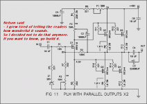
Nelson Pass thinks output caps electrolytics sound good! In PLH IRF244 amplifier.
Most of us are not afraid of using ouput caps
and build single rail clean & good and easy circuits.
But as there are a few not convinced
by what we are trying to tell, AKSA, Nordic & little me, lineup
I show you a perfect example of what another Master of Audio designs
has to say:
Nelson Pass said:
See attachment for schematic
if you REALLY would like to Follow Master Nelson advice:
- Go Build It !
Nordic said:Yep, Hugh, I also burried the "electrolytics on the output sounds bad" myth
with some simple mosfet hybrid heaphone amps...
I am yet to match that quality of SOUND in a loudspeaker driving amp...
AKSA said:Hi Lineup, Nordic,
Another advantage of these coupling caps is the opportunity afforded to hot bias the tweeter/midrange cap on the crossover. You can connect these drivers direct to the output rail at a potential around half Vcc, and thus get the benefit of better, more linear operation for the mid and high frequencies. This is a huge advantage. Then the electrolytic coupler has only bass duties; and a quality electrolytic, with a polarising voltage across it, is actually extremely good sonically.
Cheers, Hugh
lineup said:
Yeah, hugh.
you added some more benefits to using output caps
.. and in fact most any sound system uses 'Output Caps'
.. the difference is that
they are normally not called 'output caps'
They are loudspeakers crossover input caps.
Especially for higher frequency speaker drivers.
To block unwanted frequencies, to enter wrong element, woofers/tweeters,
and to keep things as constant as possible, as seen from amplifier out
Big Caps are a very simple & REALLY GOOD solution, many times.
An easy alternative to complicated 'stired up' jumbo mumbo to try to keep DC-levels in control.
And after all this DC-Coupling-Phreak-Show, a real show off in Volt DC 0.001, millivolts,
they would use a Crossover full of capacitance... anyway
Thinking they are smart
Most of us are not afraid of using ouput caps
and build single rail clean & good and easy circuits.
But as there are a few not convinced
by what we are trying to tell, AKSA, Nordic & little me, lineup
I show you a perfect example of what another Master of Audio designs
has to say:
Nelson Pass said:
..
- I grew tired of telling the readers
how wonderful it sounds.
So I decided not to do that anymore.
If you want to know, go build it.
..
See attachment for schematic
if you REALLY would like to Follow Master Nelson advice:
- Go Build It !
Attachments
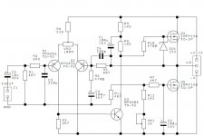
Low FeedBack amplifier.
I try to see what you want to say to me, Daniel.
Many regards to all bulgarian audio amp friends
lineup -> still going strong & a bit more wise ..day by day (hopefully )
========================
PS. Attachment is some thing for audio designers to try!!!
Low Feedback Amplifer.
Gain & feedback level is set by: R3-R6
Input stage is an original idea of mine ( Lineup Audio LAB )
Also this is some thing you can try.
I am proud of this ONE. Very!
As anyone who understands Amps .. will know! DS.
Okay.widowmaker said:offtopic
@ lineup:
please, mail me...
I try to see what you want to say to me, Daniel.
Many regards
to all bulgarian audio amp friendslineup -> still going strong & a bit more wise ..day by day (hopefully
)========================
PS. Attachment is some thing for audio designers to try!!!
Low Feedback Amplifer.
Gain & feedback level is set by: R3-R6
Input stage is an original idea of mine ( Lineup Audio LAB )
Also this is some thing you can try.
I am proud of this ONE. Very!
As anyone who understands Amps .. will know! DS.
Attachments
It should be also noted that the first transistors on that nice page Jacco linked, are actually not MOSFETs at all, but the legendary VFETs, which are actually power JFETs, depletion mode devices.
MMmmmmm VFET Power J-fets. It's too bad good semi manufacturers don't realize the potential demand for these obsolete by supply, but not by design, components. I dream of an amp with about a dozen or so pairs.

I have no doubt they would sell
Who doesn't, it will likely take me a few years more to collect sufficient numbers with an identical rating number.
Or, ask Spectral where they had their plastic V-FETs made.
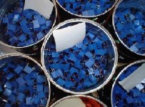
High time to tease Bogdan again, here's ~3500 in different values, can't squeeze more coffee tins in a low bit size dig. pic.
Average wholesale cost in the early '90s when they were still available $4/pc for a 56nF to $5.5/pc for 100pF.
Or, ask Spectral where they had their plastic V-FETs made.
High time to tease Bogdan again, here's ~3500 in different values, can't squeeze more coffee tins in a low bit size dig. pic.
Average wholesale cost in the early '90s when they were still available $4/pc for a 56nF to $5.5/pc for 100pF.
Attachments
jacco vermeulen said:Who doesn't, it will likely take me a few years more to collect sufficient numbers with an identical rating number.
Or, ask Spectral where they had their plastic V-FETs made.
High time to tease Bogdan again, here's ~3500 in different values, can't squeeze more coffee tins in a low bit size dig. pic.
Average wholesale cost in the early '90s when they were still available $4/pc for a 56nF to $5.5/pc for 100pF.
Jacco STOP IT!

What`s your wife saying about all that electronic parts investments??
Going back to the schematics, I see a strange thing:
It uses a TL431 Constant Volt Supply followed by a D'Arlington pair to provide s very low impedance source, and then follows it with 4,7 K Ohms and looses all the regulation? And then trusts all the current regulation of the output stage in the Vbe voltage of a BD 639, with its poor thermal coefficient?
Something strange, not to say wrong.
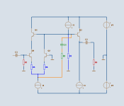
hi lateral single ended design
hi..i had a quick look at threads.. i wanna build this amp with lateral mosfets..2sk1058 or more powerful laterals.. which resistors should i change ? i want to use irfp150n for current source and 2sk1058 or more powerful laterals..
i am choosing laterals because they have smoother sound..
if you have powerful (more than 10watts )single ended lateral mos amp design please post..thanks
Attachments
hello umut
I, Lineup, started this topic about widowmaker interesting little Class A amplifier.
Looking at your circuit I do not see any Voltage.
What is your supply?
Because this is the most important factor to make more power than 10 Watt.
+ one powerful transformer to give Volt+Current, of course
You idea of using 2SK1058, Lateral for Signal Ouput
+ IRFP150N for Current source is prefectly alright!
Either you can start PARALLELLING 2SK1058
or
... for more powerful N-Channel Laterals, have a look at:
- 2SK1530
http://www.semicon.toshiba.co.jp/docs/datasheet/en/Transistor/2SK1530_en_datasheet_061120.pdf
http://www.ampslab.com/components_powermos.htm
- BUZ900, BUZ901
http://www.magnatec-uk.com/mosdata.shtml
Antony Holton, www.aussieamplifiers.com uses often BUZ900, BUZ901 in his mosfet modules
http://www.aussieamplifiers.com/modules.htm
Regards
Lineup
Lineup Lateral Class A Amplifiers projects forum
the supply is +-15 volts for irfp150s..but now i did interesting something..now there is 250watts class d lateral mos its the mosfetreally sounds good in single ended mode
http://www.classd.ltd.uk/product.php?productid=16176&cat=266&page=1
and the supply voltage is +7,5 -15 volts
but i can use exicon mos or 2sk1529
I tried PLH amp its good..but ras10 single ended amp sounds more detailed than PLH amp..i dont want output caps
i think there are disadvantages of laterals in single ended mode..but it sounds smoother and more listenable for me..
i am waiting any single ended schematics with laterals
i registered lineup forum but cant see any single ended design..
best regards
Ümit
its the mosfetreally sounds good in single ended modehttp://www.classd.ltd.uk/product.php?productid=16176&cat=266&page=1
and the supply voltage is +7,5 -15 volts
but i can use exicon mos or 2sk1529
I tried PLH amp its good..but ras10 single ended amp sounds more detailed than PLH amp..i dont want output caps
i think there are disadvantages of laterals in single ended mode..but it sounds smoother and more listenable for me..
i am waiting any single ended schematics with laterals
i registered lineup forum but cant see any single ended design..
best regards
Ümit
we will post some Lateral amplifiers
in lineup forum
you have got 1 PM from me .. with some forum info
http://lineupaudio.freehostia.com/forum
Exicon is too good alternative.
2SK1529 = 2SK1530
RAS10 amplifier looks good.
10 Watt is regarded as what is for one very good True Class A amplifier.
What expert tells.
Because of too much heat,
not very good more than 10 Watt SE, Single End.
Then better use JLH, PLH or other Push-Pull class a
for more power.
And have a look at Rod Ellott all power amplifier projects.
Have Class A MOSFET, I think.
LIST: http://sound.westhost.com/projects-1.htm
Also you have G.Kleinschmidt 10 watt Class A = Tube + 2N3055/MJ2955
The Kleinschmidt 10A
http://users.picknowl.com.au/~glenk/K10A.HTM
http://www.diyaudio.com/forums/showthread.php?threadid=119409
Nico Ras's Ras10 amp sounds great also.but i wanna try sth different.we discussed this amp with him..he did it with 2sk1058 transistors..i asked him about replacement resistors but he didnt answer my question yet.i will change the values of r3 r9 and r8..but not sure what to do.i should lower the gate voltages..
my friend tried 2sk1530 and 1529 in MJ amp(push pull class a at+-25volts)and he says 1530is terrible and 1529 is better..i dont know why he said this..they have similar input capacitance (+-200pf)and similar spesifications..
i wanna use laterals at the output..i wanna make single ended and dont want to make a push pull amp nowadays..i have 90db 20cm jbl speakers..if i have two of 10watts and two speakers it makes 103db and enough for my room..
best regards
ümit
Yes, for those JBL and 103 dB
10 Watt is just fine ... even more than fine!
Have you had a look at Nelson Pass www.firstwatt.com F4 Class A output stage?
It is 25 Watt Push-Pull .. so maybe not for you
As you mentioned those nice Exicon transistors !!!
This is one EXICON idea I have. Class A Push-Pull. 2x18 Volt DC.
http://lineupaudio.freehostia.com/forum/index.php?action=blog
I use for this idea
http://www.profusionplc.com/products/ECF10N20.html
http://www.profusionplc.com/products/ECF10P20.html
I can help you to simulate and get this RAS10 working good.
I use EWB MultiSim10 Professional Spice software.
We can test what resistor values will be better.
Just tell me, what you want .. your idea.
And I try to see what values we need.
Lineup
yes i have ewb 10 too..i will try the amp in programme.. i hope there are lateral mosfets in ewb and works true.. but i dont think that simulations are good..i used isis and ewb and results are wrong..it works only 1 or 0..
i will make push pull for fast musics and single ended for slow musics
thanks for help..
i will make push pull for fast musics and single ended for slow musics
thanks for help..
I have posted those models for exicon i use
here in www.diyaudio.com
also another member has:
EXICON 10P20/10N20 PSpice Model
http://www.diyaudio.com/forums/showthread.php?threadid=31338
regards
here in www.diyaudio.com
also another member has:
EXICON 10P20/10N20 PSpice Model
http://www.diyaudio.com/forums/showthread.php?threadid=31338
regards
here is my posted spice model
for ECF10N20 lateral mosfet, N-Channel
it is one more simple model ( not .SUBCKT )
http://www.diyaudio.com/forums/showthread.php?postid=1565701#post1565701
for ECF10N20 lateral mosfet, N-Channel
it is one more simple model ( not .SUBCKT )
http://www.diyaudio.com/forums/showthread.php?postid=1565701#post1565701
I sent you one EMAIL to Yahoo, umut
with info how things work at my audio forum
.. it is NOT like here at www.diyaudio.com
Any body who wants to publish amplifiers/circuits/schematics
and have them accessible
ONLY for those qualify as FULL MEMBERS
in our Lineup Audio community ... you are welcome
Which also means Newbie Members have
VERY restrictive, limited Rights at my forum.
For example, you have to contribute >= 5 posts,
before you can see/download any attachments/images!!!
http://lineupaudio.freehostia.com/forum
Lineup forum administrator & Web MASTER
with info how things work at my audio forum
.. it is NOT like here at www.diyaudio.com
Mainly in order to
Intellectual Property
Of any Schematics posted in my forum
Any body who wants to publish amplifiers/circuits/schematics
and have them accessible
ONLY for those qualify as FULL MEMBERS
in our Lineup Audio community ... you are welcome
Which also means Newbie Members have
VERY restrictive, limited Rights at my forum.
For example, you have to contribute >= 5 posts,
before you can see/download any attachments/images!!!
http://lineupaudio.freehostia.com/forum
Lineup
forum administrator & Web MASTERI did some additional work on this idea during the passed night.lineup said:
As you mentioned those nice Exicon transistors !!!
This is one EXICON idea I have. Class A Push-Pull. 2x18 Volt DC.
http://lineupaudio.freehostia.com/forum/index.php?action=blog
I use for this idea
ECF10N20 - npn lateral power mosfet
ECF10P20 - pnp lateral power mosfet
----
Lineup
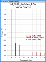
I set the gain of my mosfet class a amplifier,
dual case 2SK389BL for input stage,
to 10 = +20 dB
At 1 Watt RMS into 8 Ohm resistor
shows the following very low distortion spectrum
Attachments
- Status
- This old topic is closed. If you want to reopen this topic, contact a moderator using the "Report Post" button.
- Home
- Amplifiers
- Solid State
- 10 Watt Single End, JFET input - Lateral N-MOSFET output