The cap at Q3? Isn't the idea of a current generator is a high output impedance, not low!G.Kleinschmidt said:Hmmmmm........
Have a look at the compensation scheme used in the Dynaco Stereo 400 (indroduced in 1972). There are caps tacked on all over the place, but the one from the VAS output to the inverting input is worth noting.
http://home.indy.net/~gregdunn/dynaco/components/ST400/index.html
An externally hosted image should be here but it was not working when we last tested it.

Re: Re: Re: Re: Re: Re: Miller compensation
Hi Glen,
I know that it may seem non-intuitive that picking off the compensation capacitor from the pre-driver EF is just as good insofar as low distortion goes, but give it a try with simulation.
The key is to realize that the amount of non-linear current required to drive the non-linear pre-driver junction capacitance is the same whether the Miller capacitor picks off of the VAS directly or after the pre-driver EF. If you assume a perfect sinusoid at the output of the VAS and work backwards, determining the distortion needed in the VAS input signal to cause the perfect sinusoid at the output, you will see that it is essentially the same in either case. For simplicity, assume an ideal pre-driver EF in which the voltage signal at its output is the same as the voltage at its input.
This analysis technique is known as input-referred distortion analysis, and has some analogy to input-referred noise analysis. It helps sometimes in separating out feedback loop issues.
Cheers,
Bob
G.Kleinschmidt said:
I disagree. The input capacitance of the pre-driver (or driver, for that matter) does not change, but it's effects on HF distortion are less if it is voltage driven rather than current driven.
This is not restricted to just miller compensation either. If the compensation feedback capacitance is picked off from the VAS collector, the VAS output impedance may be only a few tens of ohms or a few hundred ohms at 20kHz.
The effects of any non-linear load capacitance (at 20kHz 100pF Xc= ~80k) connected to the VAS is then very much reduced.
Hi Glen,
I know that it may seem non-intuitive that picking off the compensation capacitor from the pre-driver EF is just as good insofar as low distortion goes, but give it a try with simulation.
The key is to realize that the amount of non-linear current required to drive the non-linear pre-driver junction capacitance is the same whether the Miller capacitor picks off of the VAS directly or after the pre-driver EF. If you assume a perfect sinusoid at the output of the VAS and work backwards, determining the distortion needed in the VAS input signal to cause the perfect sinusoid at the output, you will see that it is essentially the same in either case. For simplicity, assume an ideal pre-driver EF in which the voltage signal at its output is the same as the voltage at its input.
This analysis technique is known as input-referred distortion analysis, and has some analogy to input-referred noise analysis. It helps sometimes in separating out feedback loop issues.
Cheers,
Bob
my quick sim of similar sized VAS and follower Qs shows the 1st few distortion harmonics are indistinguishable in the VAS collector vs follower connection of the Ccomp, but at higher frequencies the follower connection has lower harmonics
at all frequencies the IMD from a relatively prime frequency test Isource on the output of the follower are lower with the outer feedback connection
the buffered Ccomp connection reduces the influence of the “feedthru zero” and as Bob has pointed out allows more aggressive 2-pole or “T-compensation” to give greater loop gain in the audio band which hugely reduces slew rate considerations over the audio bandwidth as well as reducing the distortion at the amplifier output caused by nonlinearities of the other global feedback enclosed stages by a greater amount
if your special case is using high input C follower transistors to "buffer" the VAS I'm surprised Miller comp is required at all - doesn't the follower Cin*VAS_gm give enough roll off?
I think most designers would seek out lower Cin VAS buffer/follower Qs for reduced distortion
jcx said:if your special case is using high input C followers to "buffer" the VAS I'm surprised Miller comp is required at all - doesn't the follower Cin*VAS_gm give enough roll off?
I think most designers would seek out lower Cin VAS buffer/follower Qs for reduced distortion
You're forgetting about the benefits of pole splitting.
That's one of the reasons D. Self gets such good results with just a double EF, with a VAS that essentially voltage drives the high cin drivers at HF.
Cheers,
Glen
Re: Re: Re: Re: Re: Re: Re: Miller compensation
I have no argument with that, but I think the issue is a little more complicated. You also have to consider the Miller loop gain, and factor in the effects of a dramatically raised VAS output impedance working with the driver input capacitance.
Bob Cordell said:The key is to realize that the amount of non-linear current required to drive the non-linear pre-driver junction capacitance is the same whether the Miller capacitor picks off of the VAS directly or after the pre-driver EF. If you assume a perfect sinusoid at the output of the VAS and work backwards, determining the distortion needed in the VAS input signal to cause the perfect sinusoid at the output, you will see that it is essentially the same in either case. For simplicity, assume an ideal pre-driver EF in which the voltage signal at its output is the same as the voltage at its input.
I have no argument with that, but I think the issue is a little more complicated. You also have to consider the Miller loop gain, and factor in the effects of a dramatically raised VAS output impedance working with the driver input capacitance.
Re: Re: Re: Re: Re: Re: Re: Re: Miller compensation
That's why we do simulation. Beyond a certain point, our intuition fails us and the complexity of all the considerations becomes a bit intractable.
Cheers,
Bob
G.Kleinschmidt said:
I have no argument with that, but I think the issue is a little more complicated. You also have to consider the Miller loop gain, and factor in the effects of a dramatically raised VAS output impedance working with the driver input capacitance.
That's why we do simulation. Beyond a certain point, our intuition fails us and the complexity of all the considerations becomes a bit intractable.
Cheers,
Bob
jcx said:my quick sim of similar sized VAS and follower Qs shows the 1st few distortion harmonics are indistinguishable in the VAS collector vs follower connection of the Ccomp, but at higher frequencies the follower connection has lower harmonics
at all frequencies the IMD from a relatively prime frequency test Isource on the output of the follower are lower with the outer feedback connection
the buffered Ccomp connection reduces the influence of the “feedthru zero” and as Bob has pointed out allows more aggressive 2-pole or “T-compensation” to give greater loop gain in the audio band which hugely reduces slew rate considerations over the audio bandwidth as well as reducing the distortion at the amplifier output caused by nonlinearities of the other global feedback enclosed stages by a greater amount
if your special case is using high input C follower transistors to "buffer" the VAS I'm surprised Miller comp is required at all - doesn't the follower Cin*VAS_gm give enough roll off?
I think most designers would seek out lower Cin VAS buffer/follower Qs for reduced distortion
Thanks, jcx. A good analysis.
Cheers,
Bob
Re: Re: Re: Re: Re: Re: Re: Re: Re: Miller compensation
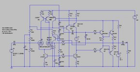
And here is a quick sim of a relatively basic 10W into 8 ohms class A design (playing The Frayed Ends Of Sanity by Metallica ATM).
THD-20 with the Miller cap connected to the VAS collector:
0.006575%
THD-20 with the Miller cap connected to the driver output:
0.007298%
Interestingly, even if I use high Cin drivers instead of the >100MHz fT ultra low Cob BJT's, the overall THD predicably increases slighty, but the HF THD is still lower with the Miller compensation cap connected to the VAS collector.
Bob Cordell said:
That's why we do simulation. Beyond a certain point, our intuition fails us and the complexity of all the considerations becomes a bit intractable.
Cheers,
Bob
And here is a quick sim of a relatively basic 10W into 8 ohms class A design (playing The Frayed Ends Of Sanity by Metallica ATM).
THD-20 with the Miller cap connected to the VAS collector:
0.006575%
THD-20 with the Miller cap connected to the driver output:
0.007298%
Interestingly, even if I use high Cin drivers instead of the >100MHz fT ultra low Cob BJT's, the overall THD predicably increases slighty, but the HF THD is still lower with the Miller compensation cap connected to the VAS collector.
Attachments
Re: Re: Re: Re: Re: Re: Re: Re: Re: Re: Miller compensation
Hi Glen,
You know that in some cases, my sims also reveal that tying the Miller cap directly to the VAS output gives lower distortion. Nevertheless, it sounds counterintuitive to me. Of course, the simulator didn't tell me why, but I think, as there are more sources of distortion involved, that they are partly compensating each other. What about that?
Cheers,
Edmond.
G.Kleinschmidt said:And here is a quick sim of a relatively basic 10W into 8 ohms class A design (playing The Frayed Ends Of Sanity by Metallica ATM).
THD-20 with the Miller cap connected to the VAS collector:
0.006575%
THD-20 with the Miller cap connected to the driver output:
0.007298%
Interestingly, even if I use high Cin drivers instead of the >100MHz fT ultra low Cob BJT's, the overall THD predicably increases slighty, but the HF THD is still lower with the Miller compensation cap connected to the VAS collector.
Hi Glen,
You know that in some cases, my sims also reveal that tying the Miller cap directly to the VAS output gives lower distortion. Nevertheless, it sounds counterintuitive to me. Of course, the simulator didn't tell me why, but I think, as there are more sources of distortion involved, that they are partly compensating each other. What about that?
Cheers,
Edmond.
Re: Re: Re: Re: Re: Re: Re: Re: Re: Re: Re: Miller compensation
Hi Edmond.
I think that in applications such a VAS driving a double EF where the driver input capacitance approaches or exceeds the value of the Miller compensation cap, the negligible or even negative returns are mostly due to the loss in bandwidth and miller loop gain when the pole-splitting effect is removed by disconnecting the comp cap from the VAS collector.
However, the way the performance swings isn’t 100% predictable even with low Cob driver or pre-drivers, so probably something as you suggest is going on.
Cheers,
Glen
Edmond Stuart said:
Hi Glen,
You know that in some cases, my sims also reveal that tying the Miller cap directly to the VAS output gives lower distortion. Nevertheless, it sounds counterintuitive to me. Of course, the simulator didn't tell me why, but I think, as there are more sources of distortion involved, that they are partly compensating each other. What about that?
Cheers,
Edmond.
Hi Edmond.
I think that in applications such a VAS driving a double EF where the driver input capacitance approaches or exceeds the value of the Miller compensation cap, the negligible or even negative returns are mostly due to the loss in bandwidth and miller loop gain when the pole-splitting effect is removed by disconnecting the comp cap from the VAS collector.
However, the way the performance swings isn’t 100% predictable even with low Cob driver or pre-drivers, so probably something as you suggest is going on.
Cheers,
Glen
Re: Re: Re: Re: Re: Re: Re: Re: Re: Re: Re: Re: Miller compensation
Hi Glenn,
I was also a little surprized to see the distortion increase by about 10% when you used the outer connection, but there does seem to be a lot going on that could make the changed connection go either way. In any case, I think that taking your simulation and that of jcx together suggests that either connection tends to make little difference in distortion, which was my only point.
If you are suggesting that the outer connection causes the pole-splitting effect to be removed, I think you may be wrong, as least insofar as the frequency response behavior of the circuitry that includes the EF subsequent to the VAS. We still get an overall dominant pole with a much higher frequency pole.
Cheers,
Bob
G.Kleinschmidt said:
Hi Edmond.
I think that in applications such a VAS driving a double EF where the driver input capacitance approaches or exceeds the value of the Miller compensation cap, the negligible or even negative returns are mostly due to the loss in bandwidth and miller loop gain when the pole-splitting effect is removed by disconnecting the comp cap from the VAS collector.
However, the way the performance swings isn’t 100% predictable even with low Cob driver or pre-drivers, so probably something as you suggest is going on.
Cheers,
Glen
Hi Glenn,
I was also a little surprized to see the distortion increase by about 10% when you used the outer connection, but there does seem to be a lot going on that could make the changed connection go either way. In any case, I think that taking your simulation and that of jcx together suggests that either connection tends to make little difference in distortion, which was my only point.
If you are suggesting that the outer connection causes the pole-splitting effect to be removed, I think you may be wrong, as least insofar as the frequency response behavior of the circuitry that includes the EF subsequent to the VAS. We still get an overall dominant pole with a much higher frequency pole.
Cheers,
Bob
Re: Re: Re: Re: Re: Re: Re: Re: Re: Re: Re: Re: Re: Miller compensation
I was only referring to the components enclosed within the Miller loop, which includes the first EF driver or pre-driver when the compensation capacitor is connected to its emitter.
When you remove the Miller cap from the VAS collector and shift it to EF driver, you then have a Miller compensation loop enclosing a stage with potentially huge open loop phase/frequency modulation with signal amplitude due to the non-linear input capacitance of the driver EF loading the VAS, which is then effectively being driven by a current source.
Bob Cordell said:If you are suggesting that the outer connection causes the pole-splitting effect to be removed, I think you may be wrong, as least insofar as the frequency response behavior of the circuitry that includes the EF subsequent to the VAS. We still get an overall dominant pole with a much higher frequency pole.
I was only referring to the components enclosed within the Miller loop, which includes the first EF driver or pre-driver when the compensation capacitor is connected to its emitter.
When you remove the Miller cap from the VAS collector and shift it to EF driver, you then have a Miller compensation loop enclosing a stage with potentially huge open loop phase/frequency modulation with signal amplitude due to the non-linear input capacitance of the driver EF loading the VAS, which is then effectively being driven by a current source.
Re: Re: Re: Re: Re: Re: Re: Re: Re: Re: Re: Re: Re: Re: Miller compensation
And that is no more a problem with the Miller capacitor connected inside or outside.
Cheers,
Bob
G.Kleinschmidt said:
I was only referring to the components enclosed within the Miller loop, which includes the first EF driver or pre-driver when the compensation capacitor is connected to its emitter.
When you remove the Miller cap from the VAS collector and shift it to EF driver, you then have a Miller compensation loop enclosing a stage with potentially huge open loop phase/frequency modulation with signal amplitude due to the non-linear input capacitance of the driver EF loading the VAS, which is then effectively being driven by a current source.
And that is no more a problem with the Miller capacitor connected inside or outside.
Cheers,
Bob
Andy L. Francis said:Guys, I'd ask how to choose the value of lead compensation capacitor properly.
Or it's offtopic here?
Re: Re: Re: Re: Re: Re: Re: Re: Re: Re: Re: Re: Re: Re: Re: Miller compensation
 Nonsense!
The non-linear input capacitance of the EF certainly does not have the same effect on the open loop frequency response of the stage(s) enclosed within the Miller compensation loop when the Miller compensation capacitor is connected to the collector of the VAS as it does when the Miller compensation capacitor is connected to the emitter of the EF.
Cheers,
Glen
Bob Cordell said:
And that is no more a problem with the Miller capacitor connected inside or outside.
Cheers,
Bob
Nonsense!The non-linear input capacitance of the EF certainly does not have the same effect on the open loop frequency response of the stage(s) enclosed within the Miller compensation loop when the Miller compensation capacitor is connected to the collector of the VAS as it does when the Miller compensation capacitor is connected to the emitter of the EF.
Cheers,
Glen
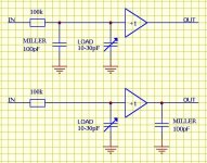
I've attached a circuit diagram of two circuits below.
With regards to the frequency response, IN through to OUT, which one (as a ratio of corner frequencies fH/fL) will suffer the greatest variation when the variable capacitor marked LOAD is varied over its specified range?
With regards to the frequency response, IN through to OUT, which one (as a ratio of corner frequencies fH/fL) will suffer the greatest variation when the variable capacitor marked LOAD is varied over its specified range?
Attachments
Non linear miller capacitance
Hello Glen
Just a point here I dont know if LTSPICE models the non linear miller capacitance accurately I think it uses just a simple capacitor to model its effect , this is the case this PSPICE. So It would be fairly safe to say that THD-20 simulation lack the effects of non linear miller capacitance in the THD sim.
Regards
Arthur
Re: Non linear miller capacitance
Hi Arthur,
I have verified that LTSPICE does indeed model a changing collector-base capacitance with Vce in a BJT. While the effect may vary a bit from one BJT to another, I can certainly say that it is there for a 2N5551.
Cheers,
Bob
PHEONIX said:Hello Glen
Just a point here I dont know if LTSPICE models the non linear miller capacitance accurately I think it uses just a simple capacitor to model its effect , this is the case this PSPICE. So It would be fairly safe to say that THD-20 simulation lack the effects of non linear miller capacitance in the THD sim.
Regards
Arthur
Hi Arthur,
I have verified that LTSPICE does indeed model a changing collector-base capacitance with Vce in a BJT. While the effect may vary a bit from one BJT to another, I can certainly say that it is there for a 2N5551.
Cheers,
Bob
- Home
- Amplifiers
- Solid State
- Bob Cordell Interview: BJT vs. MOSFET