Braco - +/-35V will give you arround 50-55W/8ohm.....
regarding quality of the amp - it is hard to say if it is good or bad - because all of us have a different taste of the music and also different speakers - one amplifier is not going to work at its best on one speaker or another different type of the speaker....so the best is to try it.... it can certainly be better made - with some improvements in this basic circuitry - but also you may like it how it sounds the way it is........
regards
daniel
Hi,
Max. PSU voltage is +/-30V for the OPA. Then I would use +/-25V supply rails.
Calculating with 5V losses (that will be more: few Volts on supply caps, 1-2V on diode bridge, and few Volts in the mosfet) the output power will be 25W-RMS on 8Ohm and 50W-RMS on 4Ohm.
So it's a 30W amp.
Max. PSU voltage is +/-30V for the OPA. Then I would use +/-25V supply rails.
Calculating with 5V losses (that will be more: few Volts on supply caps, 1-2V on diode bridge, and few Volts in the mosfet) the output power will be 25W-RMS on 8Ohm and 50W-RMS on 4Ohm.
So it's a 30W amp.
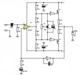
bracoraab said:I found this simple schema on the net, the opa552 can supply wiyh +- 30V and the power mosfet I think could be IRFP240 and IRFP9240?
How many watts I can get with 35 V per rail? Is this a poor quality circuit?
Cheers
Braco
Also, don't forget the OPA445, which will run off +/-45V rails, so you can get approaching 100W.
I have been looking at just such an amp recently, using the OPA445 + BUZ901/5 mosfets. Simulated performance looks good, when configured for a closed-loop gain of 2 (6dB). I will then use a driver op amp run from from +/-24V to provide the rest of the gain required.

Hi CS:
First of all, I'm rookie in electronics.
Second, my inglish is not my mother language, and please accept my apologies.
And now, to the point, we can use a regulated PS +/- 15/24V to fit opa445 and larger voltage to the power stage.
Third: can replace the TIP 29/30 with power darlingtons to drive in cascode a pair of mosfets?
PS: electronics is a hobby to me, I'm a dentist.
Cheers
Braco
Refering to: http://focus.ti.com/lit/ds/symlink/opa552.pdf (page 9)
IMOP: suggest adding, as per TI recommendations, double bypass caps on the op-amp power rails ... one electrolytic cap (10 uF or more) and one plastic cap (0.1 uF, polystyrene or polypropylene or MKT) per each rail ... this snubbs down the op-amp for the better distortion & slew rate specs. (Put the plastic caps as close as you can get to the op-amp power pins = works best.)
TI ran their numbers with +/0/- 28 VDC rails to get those better specs (examine the graphs, etc.). If you can swing that, using a common supply rail configuration for both op-amp and outputs, then you won't need exotic or complicated voltage offset control or any DC blocking caps in the audio path (other than C1 in the original schemo, at least).
Noting that the feedback & input resistors indicate ~ unity gain through the op-amp (good), so if you can keep to the original MOSFET outputs, you would have a very decent little amp. Of interest: mounting the op-amp away from the MOSFET heatsinks would allow the internal op-amp circuitry to "run free" and do it's own short circuit & thermal limiting and if you stick with the MOSFET drivers in the original schematic, since the MOSFETs are voltage followers instead of current followers like transistors, there would be virtually no heat problems (also good IMOP).
As for the final tweak, probably all that's needed other than clean power ... the variable resistor (bias) setting is done with a simple sign wave ~~ 800 to 1200 Htz, centering any crossover distortion (@ the +/- 0 VAC point) ... run 'er up to just below clipping and measure across the outputs with a cheap 'scope & dummy 8 Ohm load.
Your original schematic is vaguely similar to the aussieamplifiers.com NX series = which use discrete FETs instead of an op-amp. Good stuff, dead cold in operation, great distortion specs, plenty of guts, clear highs and solid bass ...
bracoraab said:Hi CS:
First of all, I'm rookie in electronics.
Second, my inglish is not my mother language, and please accept my apologies.
And now, to the point, we can use a regulated PS +/- 15/24V to fit opa445 and larger voltage to the power stage.
Third: can replace the TIP 29/30 with power darlingtons to drive in cascode a pair of mosfets?
PS: electronics is a hobby to me, I'm a dentist.
Cheers
Braco
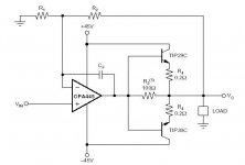
Hi Braco,
Yes I think your circuit using bipolars should work, but I would use some bias between the bases (as you did with the mosfets), to avoid crossover distortion.
You could also use higher power darlingtons such as the SAP16N/P, which would be good for the 100W version (+/-45V rails).
Also, Fasteddy's suggestions on supply rail decoupling are good ones.
CS.
And now, to the point, we can use a regulated PS +/- 15/24V to fit opa445 and larger voltage to the power stage.
Hi,
Then the OPA's output can only swing say +/-10V, and that's not enough to drive output tets running say +/-30V.
So the OPA needs equal or higher PSU voltage than output devices.
Regards,
better 2-3V higher than equal....but this is problem if you do not have aditional windins on your transformer....but the idea is nice....using filtering cap's at the output and regulated power supply for the front end that has regulated voltage a little bit higher than the output...
than equal....but this is problem if you do not have aditional windins on your transformer....but the idea is nice....using filtering cap's at the output and regulated power supply for the front end that has regulated voltage a little bit higher than the output...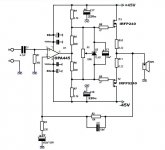
- Status
- This old topic is closed. If you want to reopen this topic, contact a moderator using the "Report Post" button.
- Home
- Amplifiers
- Solid State
- Simple schema