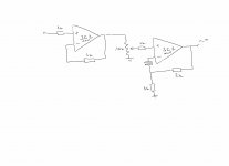
R8, R9, R10 are not present in Johns schematic, but my original modules obviously have a second pot for offset adjustment so I "borrowed" this from the ML-2 power amplifier which uses the same topology as input stage.
Thanks for the info, gk7. So, it was a bit of guesswork.. Did John "blessed" it?
Please post it, I´m curious to see it.
It's a ML-5 record amplifier. PM me with you email - I'll send you some more.
Attachments
It's a ML-5 record amplifier.
This one I knew, but what´s inside the ULD modules ?
You make it too complex. Don't use the first gain block. Come in directly to the gain pot. That is how we do it.
Thank you Mr. John Curl,
You are right - the simpler schematic is better. But in my case I have tube out CD Player which is anode out and the output impedance is around 1-1.2k which is too high to drive 10k gain pot. That is the reason to put the first gain block. Is there any other technique to avoid the use of the first module? In my case, what would you do?
Thank you in advance
Ivo
This one I knew, but what´s inside the ULD modules ?
gk7, if you look at the ML-1 manual that YOU posted, you will see that line amps in the schematics are also marked ULD-4
")
It would be best to just use an open loop dual fet follower.
Here is a nice one ;-)
http://www.diyaudio.com/forums/anal...rch-preamplifier-part-ii-750.html#post3431096
Could be made with a LSK389:
http://www.linearsystems.com/assets/media/file/datasheets/LSK389.pdf
Thank you Mr. John Curl,
You are right - the simpler schematic is better. But in my case I have tube out CD Player which is anode out and the output impedance is around 1-1.2k which is too high to drive 10k gain pot. That is the reason to put the first gain block. Is there any other technique to avoid the use of the first module? In my case, what would you do?
Thank you in advance
Ivo
located at the tube output.It would be best to just use an open loop dual fet follower.
It would be best to just use an open loop dual fet follower.
Thank you for your time!
I will try it.
located at the tube output.
It would be the best of course to be placed in the player but in my case that is impossible (there are not enough space inside)
Regards
Yes, I know. And what does this tell us about the content of the ULD-4 ? I don´t get your point.
I'm trying to say that ULD-4 = ML's "Class A Line Driver" module = John's line module, oder?
Last edited:
ferrite beads
Hi Georg,
since (I think) I have some oscillations in the preamplifier, I was wondering why did you put the ferrite beads on the resistors? Is it because you had oscillations too?
Ciao
Paolo
Hi Georg,
since (I think) I have some oscillations in the preamplifier, I was wondering why did you put the ferrite beads on the resistors? Is it because you had oscillations too?
Ciao
Paolo
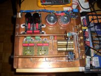
Here is a picture with the modules at work. I will do some measurements
in the next days and post them here if there is interest.
Hi Paolo,
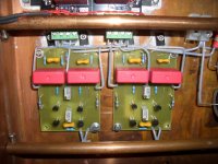
the ferrite beads were already originally there, a photo with the old resistors:
l1000109.jpg
I did not experience oscillations but only used the modules in the ML-1 with
a gain of about 10 (20 dB). They are not unity gain stable, how much feedback
you can apply (lower gain) without stability problems I don´t know, I would
estimate less than a gain of 5 is too low.
Thank you Georg. Actually I didn't change the feedback from the original design values, I have used 22k from output to inverting input and 2k2 from inverting input to ground.
Anyhow, the presence of the ferrite beads in the original design makes me think they can be useful.
Basically the preamplifier sound very well but it is missing detail.
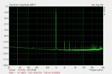
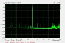
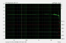
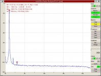
I have made some measurements using ARTA and a E-MU 0404 USB.
The first image is the loopback measurement that represents the noise/thd of the audio card, the second one is the spectrum of the output signal of the preamplifier, the last one is the frequency responce of the preamplifier.
As you can see there is a lot of garbage in the spectrum measurement of the preamplifier that makes me thinking that there could be a problem of oscillations. The frequency responce is enough extended but shows also some noise at upper frequencies.
Ciao
Paolo
Anyhow, the presence of the ferrite beads in the original design makes me think they can be useful.
Basically the preamplifier sound very well but it is missing detail.
I have made some measurements using ARTA and a E-MU 0404 USB.
The first image is the loopback measurement that represents the noise/thd of the audio card, the second one is the spectrum of the output signal of the preamplifier, the last one is the frequency responce of the preamplifier.
As you can see there is a lot of garbage in the spectrum measurement of the preamplifier that makes me thinking that there could be a problem of oscillations. The frequency responce is enough extended but shows also some noise at upper frequencies.
Ciao
Paolo
Attachments
I will try to repeat the measurements with ARTA but this
has to wait until I´m back from my holiday (beginning of September).
All I can contribute for the moment is an old measurement, it shows
about the same amount of 3rd you have, somewhat higher 2nd and not much else.
has to wait until I´m back from my holiday (beginning of September).
All I can contribute for the moment is an old measurement, it shows
about the same amount of 3rd you have, somewhat higher 2nd and not much else.
Attachments
Someone tried the new version?
An externally hosted image should be here but it was not working when we last tested it.
Borbely cascoded his line amp output stages when they were fets ( as did Pass), but both removed the output cascode becuase of a percieved loss of dynamics. However Erno indicated that his Japanese distributor and clients preferred the ouput cascode when jfets are used for the output stage. ( Borbely's Super buffer 2)
Someone tried the new version?
Why would this be a "new" version ? Looks more like a (somewhat misguided) ebay copy.
- Home
- Source & Line
- Analog Line Level
- Need to build JC 2 preamp