Thanks John !
Now, I need a RIAA with gain=60db at 1kHz for use with low level MC as Denon DL-304. It needs to use low value resistors because the noise....or....to use your Vendetta front-end as front-end here too !
eD
Hi eD
Good job, you added R34 in the RIAA but what is the actual value of that resistor?
By the way, I look forward to see your MC phono circuit.
Thanks
Hi eD
Good job, you added R34 in the RIAA but what is the actual value of that resistor?
By the way, I look forward to see your MC phono circuit.
Thanks
Hi HKC,
R34 = 33 ohm.
I use him for analysis only. I will not keep there.
R31 = 330k to adjust the open loop gain.
My simulations shown the circuit works well with R31 as low as 33k BUT pay attention on phono response because it depends on RIAA gain choose too.
Regards.
eD
Last edited:
Hi everyone,
Servo: personally I´m not afraid of using a servo (if implemented right)
and we could get rid of the 1000 uF electrolytic cap in the
feedback loop this way. On the other hand I´m not afraid of
coupling caps either (as long as they are quality polypropylenes)
and the reason why I won´t probably not use a servo is simply
space resistrictions. I will have to stick with the original
module dimensions for fitting it into my ML-1.
(If you built a preamp from scratch you won´t have this limitations
of course.)
Maybe I could implement a servo on the RIAA network board later (and
try it with and without servo this way and see what it does soundwise,
probably HCK is right and it sounds better without it, I have not done
such a comparison yet)
What I´m thinking about is to add a capitance multiplier direct
on the modules (at least for the voltage gain stages) to address
the assymetric crosstalk issue (if space limitations permit it...)
Simulation: You have 15.33mA through each input FET which is too
much for the components chosen. Using a matched quad of 2SK170V
would be an option. (most 2SK170V I have are around 14mA Idss).
I´ve read somewhere that John convinced the folks at Linear Systems
to make a higher Idss range than the V parts too, these would be
perfect here (once they are available).
0.55v before the source followers in HKC build:
Is this with the 1000 uF cap in the feedback loop (DC gain 1)
or without it ? It´s too much to be compensated with the offset
adjustment of the source followers I would say.
If you do not use the 1000 uF cap you will have a DC gain of
455 times, it will be hard to bring the offset down without a servo.
Hi everyone,
Simulation: You have 15.33mA through each input FET which is too
much for the components chosen. Using a matched quad of 2SK170V
would be an option. (most 2SK170V I have are around 14mA Idss).
I´ve read somewhere that John convinced the folks at Linear Systems
to make a higher Idss range than the V parts too, these would be
perfect here (once they are available).
Hi gk7,
I think one pair of 2SK369 will works good in that situation. Please, let me know why not if I´m wrong.
Regards
eD
Hi gk7,
I think one pair of 2SK369 will works good in that situation. Please, let me know why not if I´m wrong.
Regards
eD
Beside the fact that the 2SK369 is discontinued, even with the high Idss selection grade (grade V) you are trying to run more current through them as their Idss value probably is. This is why I recommended using a (matched) quad of 2SK170Vs. (or you lower the current of your current source until you have a maximum of 80% of Idss of your input FETs and adjust the drain resitors to a higher value until you have the same voltage across them as before).
In short 2SK369 with 20mA Idss would do, but you will not be able to find some. (If I´m mistaken and you really can source some I would like some too ;-) )
You can slightly over-bias the Toshiba j-fets, because they have such high Gm. They can put out significantly more current than Idss, ON TRANSIENTS. IF you want, you can lower the Idss on the input stage slightly, in order to be comfortable, if one is concerned. Paralleling input devices will work, but little better than a single pair, in this example, and is not mandatory.
60dB @ 1kHz
I use a MC too (Goldring Eroica LX) and having a A4E
equalizer board wich has two gain settings I tried that
with the "high" position (which is something slightly
above 50dB) and while this has enough gain for listening
it did not impress me soundwise.
I currently use a Denon AU-300LC step up and like that
combination much more. (But to be fair I must say that
the high gain position was made for low output MMs and not
MCs).
I think 60dB (80dB at low frequencies) is just asking too much from this stage,
a MC pre or a step up transformer (I think I will use
a Lundahl LL9226 mounted directly on the new EQ board.)
is a better solution.
You can slightly over-bias the Toshiba j-fets, because they have such high Gm. They can put out significantly more current than Idss, ON TRANSIENTS. IF you want, you can lower the Idss on the input stage slightly, in order to be comfortable, if one is concerned. Paralleling input devices will work, but little better than a single pair, in this example, and is not mandatory.
Thanks John.
My worry is dissipation too. Please, get my doubt off: how much dissipation can a 2SK369 ( 400mW / TO-92 ) works with, and do not deteriorates noise performance ?
eD
I use a MC too (Goldring Eroica LX) and having a A4E
equalizer board wich has two gain settings I tried that
with the "high" position (which is something slightly
above 50dB) and while this has enough gain for listening
it did not impress me soundwise.
I currently use a Denon AU-300LC step up and like that
combination much more. (But to be fair I must say that
the high gain position was made for low output MMs and not
MCs).
I think 60dB (80dB at low frequencies) is just asking too much from this stage,
a MC pre or a step up transformer (I think I will use
a Lundahl LL9226 mounted directly on the new EQ board.)
is a better solution.
The open loop gain is almost 90db. There is headroom to increase it more and this way you don´t need to use a transformer ( without ragarding sound taste )
eD
Last edited:
According to my datasheet each of the FETs in a 2SK389 can
dissipate 200mW - BTW this is a dual FET and therefore it´s
not a TO-92 case.
From the values on your simulation you have approx. 190mW for each FET already.
The simulation used 2SK369 ( my desire to use too) - not 2SK389 .
So, if 200mW is ok for 2sk369, 190mW is ok too.
But, if 100mW is better for low noise ( thanks for information John ) so, quad matched 2sk369 is the solution.
Regards
eD
Ah sorry, I confused that with the 2SK389. The 2SK369 is a higher Idss part too - the V grade is 14-30 mA and they are 400mW (and they are single TO-92). So the 15mA through them as well as 190mW should not be a problem, I think you won´t need quads in this case.
Where would you buy them (preferably matched) ? Looks like an interesting part.
Where would you buy them (preferably matched) ? Looks like an interesting part.
You can slightly over-bias the Toshiba j-fets, because they have such high Gm. They can put out significantly more current than Idss, ON TRANSIENTS. IF you want, you can lower the Idss on the input stage slightly, in order to be comfortable, if one is concerned. Paralleling input devices will work, but little better than a single pair, in this example, and is not mandatory.
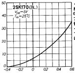
Do you refer this ?
Attachments
- Home
- Source & Line
- Analog Line Level
- Need to build JC 2 preamp