I dont understand how the output impedance of an amplifier is in series with the load. The output impedance is obviously the impedance when looking back into the amp (the impedance from the +ve terminal to -ve). How can this be in series if a loudspeaker is hooked up across the output impedance? Everyone in this forum seems to understand this except me! Any clarification would be much appreciated. Thanks
RobPhill33 said:I don't understand how the output impedance of an amplifier is in series with the load. The output impedance is obviously the impedance when looking back into the amp (the impedance from the +ve terminal to -ve). How can this be in series if a loudspeaker is hooked up across the output impedance?
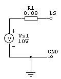
The picture below shows a simplified model of an amplifier. GND and LS are the speaker output terminals. One of them is connected to ground. On the left, we see a voltage controlled voltage source (VCVS). It is controlled by the input voltage to the amplifier. For an ideal amp, the equation Vin x gain = Vout would be true and output impedance would be zero (R1 shorted). In a real amp, things are different. Among other changes, we will have to add an output impedance (R1) in series with the voltage source.
(Don't look to close, in the drawing I used a DC voltage source as I wanted to reply fast and didn't find a symbol more accurate in the software).
If you think of the voltage source as an ideal amplifier and R1 as an external component, the output impedance is in series with the speaker. This explains why maximum output voltage decreases when you lower the load impedance.
Then, if you remember from school that an ideal voltage source has an impedance of zero between its two terminals and thus is a short, the output impedance is also in parallel with the speaker, or, in other words, the impedance you see between the two speaker terminals while "looking back" into the amplifier. This explains the damping factor.
Both is right. It just depends on the way you are looking at it.
Remember, we are talking about models of real components / circuits. They are sometimes confusing. You will never see R1 as a real component in any amplifier. It is rather a series of many impedances from power supply (or rather your local power plant) to speaker output terminal.
Hope this helps.
Attachments
Thank you for taking the time to respond. If you recall, a voltage source in series with a resistance can be changed into a current source in parallel with the same resistance (thevenin - norton). When you look at the "series" arrangement it is clear that a max voltage transfer to the load is achieved when Z(o) = 0 ohms (for a given load). Also, when you look at the "parallel" arragement it is clear that max current transfer is achieved when Z(o) = infinity. The problem is that I can not figure out the max voltage transfer from the "parallel" arrang. nor the max current transfer from the "series" arrang. I need to be able to explain it both ways. Perhaps this is outside the topic of this site, but I need to be able to explain it both ways.
Rob
Rob
RobPhill33, may I ask you why are thinking about this problem?
You thoughts works only for ideal voltage and current sources. You must take into account the max current the amp can deliver with different loads. In the theoretical world you can short circuit the voltage source. Many amps have "foldback current limitation" which makes your conversions even harder.
You thoughts works only for ideal voltage and current sources. You must take into account the max current the amp can deliver with different loads. In the theoretical world you can short circuit the voltage source. Many amps have "foldback current limitation" which makes your conversions even harder.
Models and stuff
Hi all,
The problem we have is that we would like a linear model of the things we build in order to do calculations.
A linear model is based on linear math (such as a=b*c + d*e)
It's alto easier to grasp a circuit when there is a linear model of it. The problem is that the prosess of making a linear model of a nonlinear one involves some "cornercutting" meaning that the model only have a limited range and function.
However, It't always a good thing to return to bacics when understanding what happens, and therefore I often find myself using simple Norton or Thevining generators to understand a general function of how something works.
So by all means if it helps you progress, use it. There are many conplex problems to work with, but people must proceed at their own speed using the tools they know.
hope this helps.
\Jens")
Hi all,
The problem we have is that we would like a linear model of the things we build in order to do calculations.
A linear model is based on linear math (such as a=b*c + d*e)
It's alto easier to grasp a circuit when there is a linear model of it. The problem is that the prosess of making a linear model of a nonlinear one involves some "cornercutting" meaning that the model only have a limited range and function.
However, It't always a good thing to return to bacics when understanding what happens, and therefore I often find myself using simple Norton or Thevining generators to understand a general function of how something works.
So by all means if it helps you progress, use it. There are many conplex problems to work with, but people must proceed at their own speed using the tools they know.
hope this helps.
\Jens
RobPhill33 said:Thank you for taking the time to respond. If you recall, a voltage source in series with a resistance can be changed into a current source in parallel with the same resistance (thevenin - norton). When you look at the "series" arrangement it is clear that a max voltage transfer to the load is achieved when Z(o) = 0 ohms (for a given load). Also, when you look at the "parallel" arragement it is clear that max current transfer is achieved when Z(o) = infinity. The problem is that I can not figure out the max voltage transfer from the "parallel" arrang. nor the max current transfer from the "series" arrang. I need to be able to explain it both ways. Perhaps this is outside the topic of this site, but I need to be able to explain it both ways.
Rob
Rob,
You cannot go from thevenin to norton using the same resistor of the series arrangement to put it in parallel. Remember, the two are equivalent if they have the same open circuit voltage and shorted current. For instance, if the open voltage in voltage mode is 10Vrms, and the shorted current is 2arms, the norton equivalent is a 2Arms current source with a parallel R of 5 Ohms, to give you the 10Vrms open voltage.
The max voltage transfer in the parallel mode then is that 10Vrms, but it is rather a useless piece of info, because if you load the source the voltage will decrease because the 2A current will divide itself over the 5 Omhs and whatever the load is. With another 5 Ohms load the voltage collapses to 5V rms and the load current is 1A rms.
The max current from the series arrangement follows a similar reasoning: suppose a volt source of 10V rms with a 1 Ohms Rseries, max current occurs with a shorted load: 10A rms. Of course, the output voltage then has collapsed to zero (but not the source voltage itself, which is of course still 10V rms.
Is this what you had in mind?
Jan Didden
- Status
- This old topic is closed. If you want to reopen this topic, contact a moderator using the "Report Post" button.
- Home
- Amplifiers
- Solid State
- General Amp Question