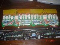
A friend bought LabGruppen FP6400 power amp. Brand new, not even 1 day, I was invited to his house, disassemble the amp, and ask me to upgrade the sound.
Anyone has experience to make better sound from this pro-amp? What to do? Changing input differential to Jfet? Change cascodes? Better CCS?
Anyone has experience to make better sound from this pro-amp? What to do? Changing input differential to Jfet? Change cascodes? Better CCS?
Attachments
An externally hosted image should be here but it was not working when we last tested it.
Personally I feel that a 6400 W amp at home at 10-100 W is not a particular good choice if you want high fidelity. This amp is made for pumping out kW's day in and day out.lumanauw said:A friend bought LabGruppen FP6400 power amp. Brand new, not even 1 day, I was invited to his house, disassemble the amp, and ask me to upgrade the sound.
Anyone has experience to make better sound from this pro-amp? What to do? Changing input differential to Jfet? Change cascodes? Better CCS?
Eva said:Uhmm...
Nice rail modulating stuf... with SMPS...
You are evil...
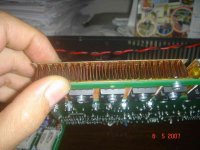
Evita, the SMPS is Flyback type but regulated....Switching converter for rails has frequency of 614Khz....dedicated high and low side drivers with floating gate driver supplies...this amp pumps out 4 X 2500WRMS=10000W.....

Hi, Kanwar,
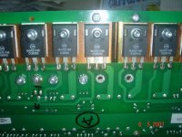
The output bipolars are different than in your picture. In your picture, the output are A1294/C3263, while in FP6400 modules, the outputs are MJW21195/MJW21196.
The owner just cut the main 220V cable head plug of this brand new amp (not even 1 day arrived in his house) just to get these 3 modules out of the amp.
Anyone got suggestion what to do? Since this amp is already disassembled (Darkfenriz tells me too late)
The output bipolars are different than in your picture. In your picture, the output are A1294/C3263, while in FP6400 modules, the outputs are MJW21195/MJW21196.
These amps sounds different than so called Hi-End amps. What makes them sound different? (Hi-End amps sound better from his POV). My friend's problem is that he could not find any Hi-End amp that has big enough rating.Personally I feel that a 6400 W amp at home at 10-100 W is not a particular good choice if you want high fidelity. This amp is made for pumping out kW's day in and day out.
Too lateI wouldn't really touch it, especially the switching part.
The owner just cut the main 220V cable head plug of this brand new amp (not even 1 day arrived in his house) just to get these 3 modules out of the amp.Anyone got suggestion what to do? Since this amp is already disassembled (Darkfenriz tells me too late
)Attachments
lumanauw said:Hi, Kanwar,
The output bipolars are different than in your picture. In your picture, the output are A1294/C3263, while in FP6400 modules, the outputs are MJW21195/MJW21196.
The amp in my picture is FP+10000Q series....
Please Post some more pics of Smps and Class-TD coils circuits....that would be good....
Meanwhile have you changed the input caps and opamp...
lumanauw said:LabGruppen, what to do?
Absolutely nothing!
Re: Re: LabGruppen, what to do?
So what if it delivers KW instead of W?
Beautiful headroom; excellent buy!
peranders said:
Personally I feel that a 6400 W amp at home at 10-100 W is not a particular good choice if you want high fidelity. This amp is made for pumping out kW's day in and day out.
So what if it delivers KW instead of W?
Beautiful headroom; excellent buy!
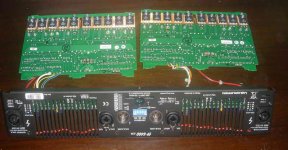
This amp is divided into 2 sections now. The input+audio modules are in my house and the casing+TDmodules+main SMPS are in my friend's house. The SMPS is really scarry. Maybe even EVA has not seen the ferrite core of this size. I will take pictures tomorrow.
Have to change the structure to get significantly better sound.
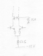
I found the first "doable" modification. The input differential is rather strange. The rails are +/-155V. But the NPN input differential are current sourced from only -15V. Also on the top of the input differential it is cascoded at +15V. I think this will produce much early effect, because the non-inverting input of the differential pair could be driven by source that can have magnitude of +/-5V or more. I'm planning to change the CCS (that feeds the differential pair) from sitting at -15V to sitting at -155V. Also to change the lower of the upper cascode's zener to the emitors of the differential pair junction (not to ground) to make the differential input pair always has 15Vce, not modulated by input signal, to minimize the early effect (changing gain by changing Vce)
What do you think about this first idea?
Yes, LM4562's are ready to be plugged. But what can be done with the main CCT structure? I often feel that changing caps and opamps are giving better sound, but not in a significant way.Meanwhile have you changed the input caps and opamp...
Have to change the structure to get significantly better sound.
I found the first "doable" modification. The input differential is rather strange. The rails are +/-155V. But the NPN input differential are current sourced from only -15V. Also on the top of the input differential it is cascoded at +15V. I think this will produce much early effect, because the non-inverting input of the differential pair could be driven by source that can have magnitude of +/-5V or more. I'm planning to change the CCS (that feeds the differential pair) from sitting at -15V to sitting at -155V. Also to change the lower of the upper cascode's zener to the emitors of the differential pair junction (not to ground) to make the differential input pair always has 15Vce, not modulated by input signal, to minimize the early effect (changing gain by changing Vce)
What do you think about this first idea?
Attachments
lumanauw said:Have to change the structure to get significantly better sound.
I found the first "doable" modification. The input differential is rather strange. The rails are +/-155V. But the NPN input differential are current sourced from only -15V. Also on the top of the input differential it is cascoded at +15V. I think this will produce much early effect, because the non-inverting input of the differential pair could be driven by source that can have magnitude of +/-5V or more. I'm planning to change the CCS (that feeds the differential pair) from sitting at -15V to sitting at -155V. Also to change the lower of the upper cascode's zener to the emitors of the differential pair junction (not to ground) to make the differential input pair always has 15Vce, not modulated by input signal, to minimize the early effect (changing gain by changing Vce)
What do you think about this first idea?
You cannot change the CCS voltage from -15V to -155V, because the CCS has integrated with muting function also...the muting of this amp is achieved by disabling the CCS....Nor you can change the cascode zener reference, because the Clip detector actually detects the signal at the emitters of cascode...if you would change the reference from ground to pair junction than i think there could be problems arised with the clip limiter itself....
lumanauw said:'m planning to change the CCS (that feeds the differential pair) from sitting at -15V to sitting at -155V. Also to change the lower of the upper cascode's zener to the emitors of the differential pair junction (not to ground) to make the differential input pair always has 15Vce, not modulated by input signal, to minimize the early effect (changing gain by changing Vce)
What do you think about this first idea?
LUMANAUW: Do NOT even THINK of GOING there!
Workhorse said:
Evita, the SMPS is Flyback type but regulated....Switching converter for rails has frequency of 614Khz....dedicated high and low side drivers with floating gate driver supplies...this amp pumps out 4 X 2500WRMS=10000W.....
Yes, the SMPS PCB layout almost screams "I'm single ended, not push pull", but it's hard to believe that a flyback of that size could produce 10KW during anything but short intervals.
Also, the 614Khz figure is hard to believe considering the parasitistic inductance of the TO-247 switches and diodes and the gate drive requirements...
Seeing that kind of stuff motivates me anyway
- Status
- This old topic is closed. If you want to reopen this topic, contact a moderator using the "Report Post" button.
- Home
- Amplifiers
- Solid State
- LabGruppen, what to do?