I have all my parts ready, but so far have been stopped by realy bad weather, two developments came out bad enough to be wiped clear straight away... under exposed... !!! (thats the downside of useing the sun as a UV source... Oh well, I have some press 'n peel if it does not work this time.... (I have that sh^%#^%y Cremolin positive, could not get my usual brand).
Out of 5 pcbs I made only the 5A heater supply for another project came out right...
My sinks are about .5 to .6W/C by my estimation... think these are big enough?
I also have a 100W sink for the regulator... (third of the price of getting another transformer), I have some 300VA 26VAC ones... and a 250VA 25VAC...
Is going to be a sick amp dissipating 160W at idle... reg + amp.
Luckily it is freezing cold winter here now... probably about 15C today... ( I am wrapped around a hot water bag now).
Without the regulator, it's only about 60W quiescent/channel. You can drop that further with +/- 18V rails.
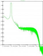
The simulation shows the PSRR at 60 dB - not very good. I could go back to the CCS on the LTP to ramp up the PSRR, but let me see how it sounds first before modding it again. With sufficient capacitance on the PSU rails, the PSRR may not be an issue in practice, and the sonics of a resistive current source on the LTP are superior to that of a CCS current source.
The simulation shows the PSRR at 60 dB - not very good. I could go back to the CCS on the LTP to ramp up the PSRR, but let me see how it sounds first before modding it again. With sufficient capacitance on the PSU rails, the PSRR may not be an issue in practice, and the sonics of a resistive current source on the LTP are superior to that of a CCS current source.
Finaly a bit of weak sun.... I put on a thicker layer of photoresist and went for a 6 minute exposure... seems to do the trick OK...
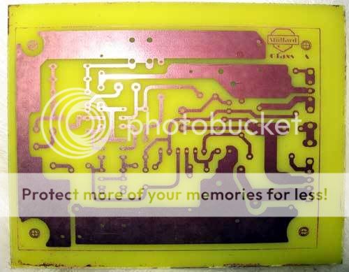
Of course I put the logo upside down and exposed the damn thing upside down...and etched it... twice....!!!!!!!!
But that saves me drilling holes...
Of course I put the logo upside down and exposed the damn thing upside down...and etched it... twice....!!!!!!!!
But that saves me drilling holes...

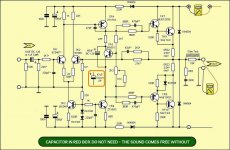
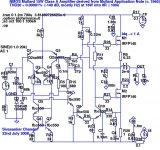
Hey Stee, give me some alternatives for transistors on the outputs... TR7-10... I have stuff like bd139/140 c5200/a1943
What does the TEXT say about TR9 and 10?
What are the notes relateing to TR1, and the 470p cap?
TR5 on main heatsink?
You resolution is a bit low, so the pic is too small to see the numbers on the meters here.
What does the TEXT say about TR9 and 10?
What are the notes relateing to TR1, and the 470p cap?
TR5 on main heatsink?
You resolution is a bit low, so the pic is too small to see the numbers on the meters here.
linuxguru said:The simulation shows the PSRR at 60 dB - not very good.
You could take a clue from the past and inject a cancelling hum.
I'm struggling a bit to understand that technique myself...
Loftin White was the classic example.
If you want to discuss my unfinished circuit, another thread.
I'm only illustrating a quick and dirty way the Mullard PSRR
could be fixed, not wanting to derail the original topic.
Attachments
I think you are adding to the topic, not makeing it worse...
I am not sure what the symbol under the output fet is...
What kinda numbers are we looking for as values for those inductors?
would seperate supplies for the front end help?... thinking PCB mount trannies... or even just a bit of extra regulation for those parts a la DX style...
I am not sure what the symbol under the output fet is...
What kinda numbers are we looking for as values for those inductors?
would seperate supplies for the front end help?... thinking PCB mount trannies... or even just a bit of extra regulation for those parts a la DX style...
Nordic: The artwork image was laterally inverted? That's not a problem for any of the components except the output MOSFETs - you just have to rotate the the small signal devices by 180 degrees before mounting them. It does cause an issue for the output devices because of the heatsink orientation, but that can be resolved by mounting on the solder side, as you've done with all the other components.
Kenpeter: OK, I'll look at it in due course. For now, the quick and dirty solution is to use larger filter caps and maybe a pi-filter.
Kenpeter: OK, I'll look at it in due course. For now, the quick and dirty solution is to use larger filter caps and maybe a pi-filter.
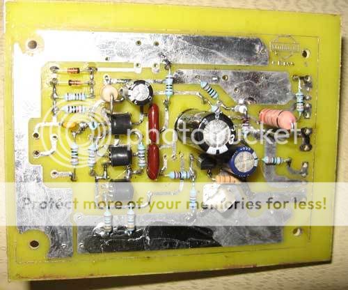
Lol, yeah I was so stupid... so far soldering to the top seems to be fine... and actualy opened my eyes to the fact that we could butterfly the two output transistors to the sides, with a minor track adjustment.
You know, designing PCB's is a very good school at haveing to process each component's operation, how hot will it get...? how far will it radiate? And building it so far suddenly I realised that these two little transistors are constantly dissipating more than my HRII with big TO3P output packages, does at peaks...
(Sorry let me just move my soldering sponge, it dried out, and looks like a cookie... I'm hungry)
Arrangeing them as closely as I did may, very likely, be problematic... we'll see when we get there...
I guess if buying a transformer for the thing, I can settle for about 180-200VA per channel.
I am also playing in my spare time with a processor that connects to a USB stick for programming, that can be used to track temperature etc through the onboard ADC...
HOW can we add adjustable biasing?
One way to add adjustable biasing is to make R16 a preset, say 20k or 47k. Set it initially around 10k, then adjust it (using an oscilloscope) such that neither transistor goes into completely into cutoff at maximum output swing (~ (Vsupply - 3 V) amplitude) into a dummy load (power resistor) of 8 ohms.
Generally, higher the quiescent current, the lower the 3rd and higher-order distortion components. The simulation indicates that 1.2 to 1.5 A is sufficient - if that's too hot, you can lower the quiescent current to 0.5A - 1A, and it will operate in Class AB (Class A for small swings).
Generally, higher the quiescent current, the lower the 3rd and higher-order distortion components. The simulation indicates that 1.2 to 1.5 A is sufficient - if that's too hot, you can lower the quiescent current to 0.5A - 1A, and it will operate in Class AB (Class A for small swings).
Nordic said:Hey Stee, give me some alternatives for transistors on the outputs... TR7-10... I have stuff like bd139/140 c5200/a1943
What does the TEXT say about TR9 and 10?
What are the notes relateing to TR1, and the 470p cap?
TR5 on main heatsink?
You resolution is a bit low, so the pic is too small to see the numbers on the meters here.
HI
this copule c5200/a1943 it's very good
his drivers are D600 and B631
also you can use MJE340/350
Another modification to the previous Mullard MOSFET circuit - basically:
1) A simple voltage follower to isolate the LTP stage from the VAS, a la Douglas Self. This alone gains about 15-20 dB in THD20.
2) A Wilson current mirror instead of the simple current mirror on the LTP. Not much gain in THD20, but it improves the sonics a bit.
3) A few biasing changes to improve performance with jelly-bean bc550c BJTs.
The LTP PNPs can be substituted with jelly-bean bc558/559/560 or 2sa970/1015, at the cost of about 2-3 dB in THD20. With the 2sa992 shown, it simulates with H2 at ~ -143 dB and H3 at ~ -148 dB at 16W into 8 ohms || 100 nF.
All small-signal NPNs (except the VAS Q8) can be substituted with jelly-bean 2sc1815 or hi-beta 2sc3112, with an impact of +/- 10 dB on THD20. Other alternatives are 2sc2240 and 2sc1845 (not simulated).
Attachments
BTW, this month is the 50th anniversary of the publication of the original circuit with this sliding bias topology in 1958:
Pawling, J.F. and Tharma, P. "A 4.5W sliding bias amplifier using an OC16", Mullard Technical Communications, Vol.4, No.31, July 1958.
Considering that the BJT had just been invented in the early 50s, and power BJTs like germanium OC16 had shown up only in 1956, this seems to have been a very early seminal paper in solid-state amplifier design, along with the early work by H.C.Lin.
I don't suppose that the original authors could have imagined in their wildest dreams that their sliding-bias topology would still be viable and relevant (in updated forms) half a century later!
Edit: Could somebody who has the printed version of the 1958 article please scan and upload just the schematic (copyright fair use)?
linuxguru;
I have learned a lot from studying your simulations - but my question is:
Have you actually MADE and LISTENED to your designs ???
I find myself agreeing with Mooly that 'armchair' designers seem to have taken over DIYAudio, and people who actually contribute their real-world expertise are given short shrift.
I speak not only of the well-known designers such as John Curl, Bob Cordell, Charles Hansen, etc. but others like xpro and ilimzn.
And what is it with these Australians and their obsessiveness with IP over their designs ???
Sure, I have built several of the designs that I have simulated, but only Class AB/B for practical reasons. One of them is an AKSA-workalike which met or exceeded my expectations when I listened to it.
For Class A, the two main simulated designs that I have worked on are:
1) Modifications to the input stage of the JLH 1969 to increase loop gain and lower distortion;
2) The Mullard sliding bias (this one), which is further along, with two completed PCB layouts (initiated by Nordic) of the previous Hexfet version.
I will eventually build one of the two (most probably the previous version), but just wanted to see how far this topology could be pushed without over-complicating it. Apparently, a good 20-35 dB on THD20 - which is a useful margin to keep and trade off, if necessary, for stability in practice.
Note that I prefer to use jelly-bean commodity parts wherever possible, which contributes to the ease of practically realizing my circuits by almost anybody who peruses it, and is familiar with the art/practice. Anybody can modify it, improve it, build it and verify whether it sounds good enough.
This differs from other armchair experts who prefer exotic unobtainium, which often provides a convenient cloak of plausible deniability, in case somebody actually builds it, substitutes components and finds it unsatisfactory.
As for the Aussies, I have had useful inputs in the past from Hugh Dean (AKSA) and Glen Kleinschmit, who have contributed useful suggestions to improve some of my earlier simulated designs. I have in turn contributed ideas to Hugh, and I have no problems if they want to keep their own secret sauce, well, secret.
For my own part, I have mostly been improving on earlier topologies and ideas originated by others, so I feel no immediate need to keep my contributions secret for now.
linuxguru;
Excellent response - I appreciate your integrity and expertise.
I am 52, have an MSEE, played guitar for 40 years, and my efforts are to make a simple musical instrument amplifier.
I cut my teeth on valves (tubes), germanium transistors, etc.
In response to those who diss Ge, let me say that my (now deceased) father's old Phillips reel-to-reel with germanium transistors id the most satisfyingly musical source in my system.
My system has not changed over the last 20 years - Technics turntable with SME3009 and Ortofon VMS20E cartridge; Kyocera R-40 receiver;
Magnavox CD player (plays CDR too !); AudioPulse speakers; TEAC 3-head cassette; not to mention VHS-HiFi and Hi8, used for audio archival.
Surprisingly, being a Hendrix/Blackmore/Beck etc. fan, I like vacuum tube guitar amplifiers, but found some solid-state units that are pretty good sounding - my current unit is an extremely simple Traynor TS-25 with standard Lin Darlington output. I have used this as a mule for trying out some of the topologies proposed here at DIYaudio.
I applaud your usage of standard devices, rather than "unobtanium".
Balaboo,
This forum is ideal for armchair designers, since working models cannot be heard or seen..... no surprises there.
I guess it's cultural.......
Cheers,
Hugh
This forum is ideal for armchair designers, since working models cannot be heard or seen..... no surprises there.
And what is it with these Australians and their obsessiveness with IP over their designs ???
I guess it's cultural.......
Cheers,
Hugh
Aksa;
Point taken and understood - I use the Simetrix simulator that Geoff (of JLLH fame) turned me on to, but have drawn on my experiences of 15 years ago, when I used to design PC/workstation motherboards and PCI cards.
I always insisted that the junior engineers NEVER use autoroute, no more than 4-layers, and learn about striplines...
Funnily enough, using point to point style wiring on a bare board (can't afford to have PCB's made - long story) seems to give me the best results - no problem with quality electrolytics, and always use mica capacitors for the VAS. I use a combination of the standard Miller compensation capacitor and the JLLH style feedback capacitor to the inverting input.
I have also discovered that the Australian style Zobel/Boucherot network works well (the parallel L/R with series C, speaker across C).
- Status
- This old topic is closed. If you want to reopen this topic, contact a moderator using the "Report Post" button.
- Home
- Amplifiers
- Solid State
- Mullard SS power amplifier