Hi Guys,
A friend of mine has this Perreaux 9000B amp and one channel is not working properly. I checked the low voltage leg of the power outputs and all are the same except for the -side of the left channel. The good channel and positive side of the left all read .499v. The -side of the bad channel read .348v. I need a schematic to maybe see what component might be causing this unless one of you happen to know.
Thanks, Terry
Hi Terry,
I haven't got a schematic I'm afraid, but you might try contacting the company for a copy (www.perreaux.com). The amp is over 20 years old now, so there are probably no trade secrets hidden in there.
There's a schematic for the 3000B model on this forum somewhere, that you should be able to search and find. It looks like a fairly generic version of Hitachi's original app. notes, and I suspect the the 9000B is very similar, but with a few more mosfets on the output.
Good luck, but be careful inside the amp. They have high voltage rails that can give you quite a belt. I suggest that you keep one hand in your pocket when it's powered up.
Andy
8000c
Just opened up my blown 8000c:
One 2SK176 FET blown with Gate to Source short reading 500 ohms. I see these are quite difficult to get.
How critical is matching the output devices: can I replace just one of the five FETS with a good used 2SK176 or Exicon/Semelab new one; or do I need five new matched FETs?
Alternately, can I just take out 1 FET from each group and run with a RMS power of 400W rather than 500W? I probably never come close to using even 50W on account of neighbors and wife.
Does anyone have a bias adjust procedure for these amps?
Thanks,
Ezekiel
Hi Guys,
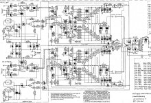
Long tome no see. Sorry for resurrecting such an old thread but I am finally getting around to trying to fix this amp. I did get the Schematic from Perreaux and have attached it here in PDF.
The voltages shown I will list here.
Assuming the rail voltages are within spec (+/- 110 volts) then this is what you should have:
Q5:
base = 107 V
Emitter = 107.5 V
Q3:
Base = -108.5 V
Collector = -54 V
Emitter = -109 V
Q4:
Base = -108.5 V
Emitter = -109 V
Q1 & Q2:
Emitters = 0.7 V
Quiescent current from the power supply under no load should be 170 mA.
There should be 0.6V across RV1 (the bias adjust preset) from one end of the pot to the other (ignoring the wiper)
OK, so here is what I have so far;
First of all, I have +/-120v on the rails instead of 110. I'm not sure why. the Schem shows 84vac on the transformer and mine is showing 77v under load.
Anyway, here are the voltages I am reading on the bad board;
Q5:
base = 115.3 V
Emitter = 115.8 V
Q3:
Base = -116.6 V
Collector = -35 V
Emitter = -117.2 V
Q4:
Base = -116.4 V
Emitter = -117.2 V
Q1 & Q2:
Emitters = 0.744 V
I have 0.874 V across RV1.
Truth is, the good board measures almost exactly the same on all these measurement points.
Where they differ is in the outputs. the gates of the good board read +/- 0.490 V, however the gates on the outputs of the bad board read + .489 V and on the - side they read 308 mv.
Any help will be greatly appreciated.
Blessings, Terry
Attachments
Last edited:
When you load it ofcourse the voltage will drop a bit - should not be alarming.First of all, I have +/-120v on the rails instead of 110. I'm not sure why. the Schem shows 84vac on the transformer and mine is showing 77v under load.
About the differnece in rail voltage: A couple of years ago, in some parts of Europe they adjusted the supply voltage so that all countries have the same voltage. So before some EU countries had 220V and other 240V. In Denmark we had 220V and it is now 230V. This means that old amplifiers suddaently have 5% higher secondary rail voltage.
Could it be a similar scenario in your case?
There should be 0.6V across RV1 (the bias adjust preset) from one end of the pot to the other (ignoring the wiper)I have 0.874 V across RV1.
Where they differ is in the outputs. the gates of the good board read +/- 0.490 V, however the gates on the outputs of the bad board read + .489 V and on the - side they read 308 mv.
Blessings, Terry
It could be the DC-blocking capacitor in the feedback loop (C4) that has failed and is now shorted.
Replace that to start with.
Best thing to do is actually to replace with a bipolar capacitor, which it should have been from the beginning.
You could use two 1000uF polarized caps with the two + leads connected between them, and the two - leads as the new terminals.
It could also be a case of one MOSFET has given up, or is not open. I had similar case recently on an Accuphase P260 (year 1979) with almost the same MOSFETs. Some of them had given up ( open connection) leaving only half the current towards one of the rails because only MOSFET was conductíng, and two conducting towards the other rail.
Makes sense?
So you should check that all the sourceresistors have current running through them, preferebly and equal value +-20%
If anyone of them has an voltagedrop wich is zero or much more than the other ones, it could mean that this MOSFET needs replacement.
If all thing are good, then you could try - carefully - to adjust VR1.
Adjust for a little more bias to make sure all the MOSFETs are safely in an open state. It could just be a small turn and everything could fall into place.
This should however be taken car of by the DC-blocking capacitor in the feedback loop, so start with that.
Regards Henrik
Last edited:
This should however be taken car of by the DC-blocking capacitor in the feedback loop, so start with that.
...Reading your messages a bit deeper I see now that you mean the bases of the MOSFETs that have these 0.4-0.5v voltages. ( I read it as the DC offset of the whole stage!)
Well...these voltages doesn't seem to far off ... so what is the real problem?
How is the channel not working? Distorted sound or no sound?
Is the offset of the channel below 30mV?
Is the Idle current around 170mA after 30 minutes without load?
(Measure voltage over the source resistors, divide by value, add all results together)
Hi Nrik,
Please post as much as you like. I need all the help I can get.
Yes, it is the base of the MOSFETs on bad channel that the negetive side that are only reading -308mv. The possitive side is 0.470V. The bases on the good channel are -0.424 and +0.424.
Also, on the good channel, I am getting about -022mv offset on the output and +029mv offset on the bad channel.
There are only main fuses. No fuses to pull on the PCB.
EDIT; I am plugged into a different outlet this morning and the Main rails are +/- 117V
Blessings, Terry
Last edited:
Hi Terry, have you got a 'scope? If you have, hook the bad channel up to a dummy load and feed it a 1kHz sinewave from an oscillator. Monitor across the dummy load with the scope and slowly increase the input signal. If one half of the sine starts to limit before the other, then you have one or more leaky or open cct fets. All this assumes that it doesn't blow fuses when powered up.
Good luck.
Steve.
Good luck.
Steve.
I should have stated earlier that the bad channel does make sound but it is distorted. I have to believe that it is not going work properly until I can discover why I have only -300mv where I should have -0.5V. I don't know where that voltage comes from. Is it generated by the MOSFET or Q4?
Thanks, Terry
Thanks, Terry
Last edited:
I do have a scope but don't remember how to hook it up. It was 6 years ago that I was playing around with this stuff and was only just getting the hang of it then. Also no sinewave generator.
When you say "leaky fets" are you refering to the MOSFETs? Those Hitachi's are getting hard to find.
When you say "leaky fets" are you refering to the MOSFETs? Those Hitachi's are getting hard to find.
Last edited:
Hi Terry, yes, I am referring to the mosfets. If you have a good quality dmm that can read millivolts, with the amp powered up measure the voltage across each gate stopper resister. Good fets should show a fraction of a millivolt or nothing. A faulty fet will draw gate current which will show as a voltage drop across the gate stopper. Check the resisters first to ensure that none are open or shorted. (This check with the amp powered down.) Otherwise you will have to pull the fets and test each one.
Regards,
Steve.
Regards,
Steve.
Okay great.
So to narrow the fault options down, it could be:
1) Too low bias - adjustment needed.
2) defective MOSFETs ( one or more)
The voltage is comming from the current through the VR1 potentiometer, and its setting.
So to solve 1) carefully increase the bias voltage with by adjusting VR1 to a slightly higher ohmic value, and see if you can hit the magic -0.424 or close to it. If the bases at the P-channels stays at -0.3V and the adjustment only increases the N-channels bias, then as SRH states you probably have one or more defective MOSFETs in the P-channel range (2SJXX).
To solve 2), you could try to operate the MOSFETs 1 pair ( N+P) at a time, by pulling out the other ones (switch the amp off before pulling them of course). As long as you are not loading the amp it is no problem at all to operate it with only one pair, just make shure you have the same amount of N-channels as P-channels mounted at all times.
When you find the P-channel(s) that is/are defective and you can isolate it/them and operate without, you should experience perfect operation, both measurement-wize and sound-quality-wize.
If it is only one defective unit, the alternative to hunting down original spareparts is to remove it completely, and also pull out one N-channel even though they might all be working fine, to have the symmetry. Pull one pair form the other channel also.
Of course this is not the optimum solution, but four pairs is still decent and can still deliver a huge amount of current. So while you hunt for spares you can use the amp fully. (Just avoid throwing a party with 3 pairs of B&W or Magnepan speakers in parallel)
You can increase
First of all, I have +/-120v on the rails instead of 110. I'm not sure why.
Standard mains voltage in the US has gone up from 110-115Vac to 120-125Vac.
In the case of the Perreaux, that's not a fortunate event, the J56/K176 only handle 200Vdc between drain and source.
(good to see you're healthy and still kicking audio, Terry)
Thanks,
Is there a way to test the MOSFETs out of circuit? I just remembered that I have a old Soundcraftsmen that I never could get going. It has a pile of those MOSFETs in it but I would need to be able to test them.
Steve,
When you say gate stopper are you speking of R17- R26? If so, they all measured 218r to 220r. They measured 0000.0mv with amp powered up.
Thanks, Terry
I did test the
- Status
- This old topic is closed. If you want to reopen this topic, contact a moderator using the "Report Post" button.
- Home
- Amplifiers
- Solid State
- Perreaux 9000B schematic?