Hi Maxpou
I suppose you have a scope otherwise...
Always put a resistor load in parallel with the cap ( 8 ohms is the standard one used and ususally represents the nominal impedance of lots of speakers).
Use an input 10 KHz Square wave and adjust the level to have an ouput of about 4V peak. Do not exceed 10 V otherwise you may have your cap to explode!!
 and it smells like HELL !
1) Try first with no cap in parallel
2) then try with the small value of 1 nF then increase the value with 2.2nf, 4.7nf, 10 nf, 22 nf, 47 nf, 100nf, 220nf, 470 nf, 1uf, 2.2uf.
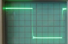
Normally you should see different output shapes going from a perfect square wave for very low cap values (1 nf, 10nf, 22nf ...).
After that you will reach a point in caps value where sometimes the square shape may start to deteriorate a bit on the edges. It is still OK.
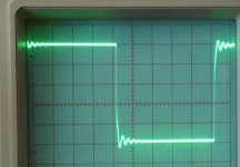
After that possible roughness on the edges, you will start to see overshoot (maybe 220 nF or more) but it should be damped.
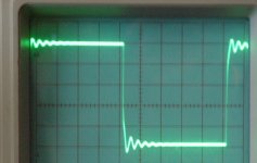
Note: If you begin to see oscillation on the square wave for a specific cap value just stop the test at this value since it means your amp is not stable and depending on the oscillation it could eventually damage the amp... But you can test the other cap values to see the extent of the stability problem if any.
Just send us some pictures if you can (2 uf, 100 nf, 4.7nf for example).
Good luck!
I suppose you have a scope otherwise...
Always put a resistor load in parallel with the cap ( 8 ohms is the standard one used and ususally represents the nominal impedance of lots of speakers).
Use an input 10 KHz Square wave and adjust the level to have an ouput of about 4V peak. Do not exceed 10 V otherwise you may have your cap to explode!!
and it smells like HELL ! 1) Try first with no cap in parallel
2) then try with the small value of 1 nF then increase the value with 2.2nf, 4.7nf, 10 nf, 22 nf, 47 nf, 100nf, 220nf, 470 nf, 1uf, 2.2uf.
Normally you should see different output shapes going from a perfect square wave for very low cap values (1 nf, 10nf, 22nf ...).
After that you will reach a point in caps value where sometimes the square shape may start to deteriorate a bit on the edges. It is still OK.
After that possible roughness on the edges, you will start to see overshoot (maybe 220 nF or more) but it should be damped.
Note: If you begin to see oscillation on the square wave for a specific cap value just stop the test at this value since it means your amp is not stable and depending on the oscillation it could eventually damage the amp...
But you can test the other cap values to see the extent of the stability problem if any.Just send us some pictures if you can (2 uf, 100 nf, 4.7nf for example).
Good luck!
Hi Max,
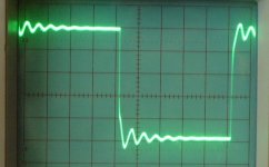
that is oscillation coming in and getting stronger as capacitance increases.
You need to attend to the stability components to increase the phase margin.
I still wonder why the frequency drops as you increase the capacitance? It looks like an inductance+ increasing capacitance ripple.
Any other thoughts from out there?
AndrewT said:...You need to attend to the stability components to increase the phase margin.
...
Any other thoughts from out there?
Hi Andrew,
I have noticed Max that the corner frequency looked quite high and it seems that Max uses a small 47p at input of amp. Without knowing the series resistance at input, it can be a -3db frequency point over 1 MHz or more...This is not helping to get a safe stability...
I also think that Max should continue the testing with 1uF and 2.2uF to reveal more...and try to filter more the input frequency...
Aligator cables- if used- to connect test load are sometimes a bit inductive and resistive too...
Hi Fab,
I have seen, but not yet tried, the method of injecting the test signal after the input filter.
I presume the reason is to deliberately provoke the amplifier into oscillation using very fast rise times, particularly when using squarewaves.
If one were to inject prior to the filter this reasoning fails.
I have seen that the low pass filter cap interacts with the operation of the amp by changing a pole and making the amp more stable. I can't get my head around this mechanism so my description is likely to be technically incorrect. But, it prompts the question.
If the cap becomes part of the amp stability/pole setting system, then removing it to inject a fast test signal is not a valid method. Do we leave the filter cap in place and let the low impedance of the cap load the oscillator source?
Andrew, I've read that the input capacitor helps to increase the bandwidth of the input stage via some kind of feedback mechanism. I have only seen very brief statements of this. I have wondered about this for a long time, because I haven't been able to get a handle on this, either. Leach says his input cap is part of the stability mechanism of his amp, also.
AndrewT said:Hi Fab,
I have seen, but not yet tried, the method of injecting the test signal after the input filter.
I presume the reason is to deliberately provoke the amplifier into oscillation using very fast rise times, particularly when using squarewaves.
If one were to inject prior to the filter this reasoning fails.
I have seen that the low pass filter cap interacts with the operation of the amp by changing a pole and making the amp more stable. I can't get my head around this mechanism so my description is likely to be technically incorrect. But, it prompts the question.
If the cap becomes part of the amp stability/pole setting system, then removing it to inject a fast test signal is not a valid method. Do we leave the filter cap in place and let the low impedance of the cap load the oscillator source?
Hi Andrew
The input cap is part of the whole amplifier transfer function. This can be easily seen with a simulator where you verify the gain frequency response and the phase response and calulate the phase margin. The difference with the input cap can also be observed in a practical amp using the 10KHz square wave into RC load (unless you have a very big phase margin in the first place).
Ideally, one might try to get a stable amp without the need to increase the value of the input cap, but since the input cap is required anyway to filter possible hi F artefacts coming at input of amp, is it a real benefit to try to compromise things to get perfect stability wihout it?
Furthermore, this hi F content is not audio content anyway...
if you have a dual trace scope it is helpful to take the gain measurement out to 150 - 250kHz and measure the phase (easier said than done) -- plot both -- take two aspirins and call me in the morning -- especially if you've done this at full power (this is how to tell whether your amplifier barks or sings)
(it will definitely tell you how to fix the stability problem).
(it will definitely tell you how to fix the stability problem).
I agree with all the above.fab said:The input cap is part of the whole amplifier transfer function. This can be easily seen with a simulator where you verify the gain frequency response and the phase response and calulate the phase margin. The difference with the input cap can also be observed in a practical amp using the 10KHz square wave into RC load (unless you have a very big phase margin in the first place).
Ideally, one might try to get a stable amp without the need to increase the value of the input cap, but since the input cap is required anyway to filter possible hi F artefacts coming at input of amp,
What do I read into this following part?
If the amp is bordering on instability when the phase margin is reduced due to feeding a capacitive, then this will show more readily by feeding a squarewave to the input. But if one feeds a square wave to the input of the low pass filter then it is no longer a squarewave (it is a rounded corner approximation with much of the extended hi frequency content attenuated). I ask where does one inject the test signal? and does one accept that the test signal generator will see the filter cap as a load? My Rs is 300ohms and a filter cap will be significant. I do not want to ALTER/MODIFY the amp just for the test, I believe that it should be tested as built.is it a real benefit to try to compromise things to get perfect stability without it?
Furthermore, this hi F content is not audio content anyway...
How does one set up the oscilloscope to measure phase angle? What other equipment is needed to achieve reasonable accuracy.jackinnj said:if you have a dual trace scope it is helpful to take the gain measurement out to 150 - 250kHz and measure the phase (easier said than done) -- plot both -- take two aspirins and call me in the morning -- especially if you've done this at full power (this is how to tell whether your amplifier barks or sings)
(it will definitely tell you how to fix the stability problem).
BJTs to 200kHz! 100kHz yes, but further out?
AndrewT said:
How does one set up the oscilloscope to measure phase angle? What other equipment is needed to achieve reasonable accuracy.
BJTs to 200kHz! 100kHz yes, but further out?
You can do it if you have access to the horizontal and vertical deflection plates -- remember how to do a lissajous figure with a scope ? -- see the attached.
sin(theta) = +/- (b/a)
If you get two high speed comparators you set up a circuit where the diference in trip time feeds an integrator and the resulting voltage is linearly proportional to phase angle -- this is how Hewlett Packard did it with their 3575A meter (and Fluke as well.) (Somewhere on my site I linked an Intersil article which described a phase-meter acurate to a fraction of a degree at 10 Megahertz -- I built the circuit but regrettably Intersil stopped making the dual long-tail pair which I used as a comparator.)
If you know phase and gain you can derive a stable compensation scheme which doesn't over damp the amplifier.
Attachments
Regarding the points raised about the requirement for the input filter capacitor, I noted during sims and in testing that my amp definetley performs better with it (1k and 1nF = pole at 150kHz). The reason its there is to ensure that the small signal bandwidth of the input signal is limited to a lower value than the forward loop of the of the amplifier - i.e. the input signal rise times after the input filter are always slower than the intrinsic rise times of amp without the input filter.
I note that Bob Cordell does not believe an input filter (other than to remove RFI) is necessary so I may be missing an trick here - Bob/Nelson/John - can any of you comment on this for us?
I note that Bob Cordell does not believe an input filter (other than to remove RFI) is necessary so I may be missing an trick here - Bob/Nelson/John - can any of you comment on this for us?
- Status
- This old topic is closed. If you want to reopen this topic, contact a moderator using the "Report Post" button.
- Home
- Amplifiers
- Solid State
- testing for stability