Ok, that can only be slew rate limiting but its odd as this amp is pretty fast and 50 khz square waves should be possible. I think you can ease a little on the value of Cdom cap as well which will increase the slewrate. The design has low openloop gain so little compensation is needed.
If you used say a 5 volt p-p does the effect dissapear ??
If you used say a 5 volt p-p does the effect dissapear ??
Hi Maxpou
Have you tried reducing the value of R32 (between Power Gnd and input/feedback Gnd) from 10 ohms to 0 or 2 ohms to see the effect on the overshoot/ripple...
Also, you can see the phase margin using a scope with channel 1 on input signal and channel 2 on output signal and doing a Sinus frequency sweep from 10KHz to 500 kHz.
Fab
Last edited:
Ok, that can only be slew rate limiting but its odd as this amp is pretty fast and 50 khz square waves should be possible.
you are right, the amp is not as fast, wrong test point. I will post another picture soon. Maxpou
Hi Maxpou
Have you tried reducing the value of R32 (between Power Gnd and input/feedback Gnd) from 10 ohms to 0 or 2 ohms to see the effect on the overshoot/ripple...
Also, you can see the phase margin using a scope with channel 1 on input signal and channel 2 on output signal and doing a Sinus frequency sweep from 10KHz to 500 kHz.
Fab
Hi Fab,
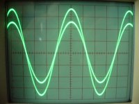
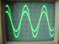
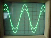
some picture of phase margin without output inductor with 6.8Ohms load. Maxpou
Attachments
Last edited:
Hi Maxpou
Have you tried reducing the value of R32 (between Power Gnd and input/feedback Gnd) from 10 ohms to 0 or 2 ohms to see the effect on the overshoot/ripple...
Also, you can see the phase margin using a scope with channel 1 on input signal and channel 2 on output signal and doing a Sinus frequency sweep from 10KHz to 500 kHz.
Fab
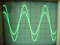
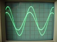
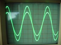
another picture of phase margin with output inductor 2.5uH. Maxpou
Attachments
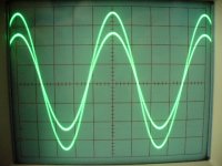
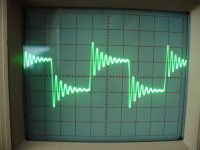
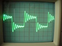
Another picture with 10Khz square wave and 6.8ohms//1uF. I have a good test point. Maxpou
Attachments

Last edited:
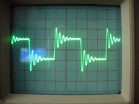
Another picture with 10Khz square wave and 6.8ohms//1uF. I have a good test point. Maxpou
Why the ripple difference between the scope traces if the same test is performed

Also, your sine traces are for which frequency? Show at least -3db corner frequency or higher.
Fab
Last edited:
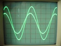
this is not phase margin...........you can see the phase margin using a scope with channel 1 on input signal and channel 2 on output signal and doing a Sinus frequency sweep from 10KHz to 500 kHz.
The difference in the traces shows the phase shift from input to output.
You can read off the "effective time delay" of the amplifier over the frequency range from 20Hz to 20kHz. Expect 1us to 2us and for that to change smoothly as you change test frequency.
this is not phase margin.
The difference in the traces shows the phase shift from input to output.
You can read off the "effective time delay" of the amplifier over the frequency range from 20Hz to 20kHz. Expect 1us to 2us and for that to change smoothly as you change test frequency.
That is correct, it is not the phase margin per say. I should have been more precise on the forum.

In fact, one should inject the frequency at which the output amplitude is the same as input amplitude (gain =1). Then verify the phase shift between input and output . The output amplitude should be less than input before shift is 180 degrees. Of course one must pay attention to quickly turn off the amp in case it reaches oscillation (and use small input amplitude for test)...
Fab
Last edited:
Square signal = blowing OPS
Hi,
I've build an amp on a prototype board (Front End is connected to driver section and OPS with wires of +-10cm).
Today I wanted to perform a square wave test:
1 Input is connected to functiongenerator and set to a squarewave of 0.15v
amplitude
2 Output is connected to a 20W/4Ohm resistor
When powering on the amp, both rail fuses blown and took the output fet's with them.
Can anyone help find the reason for this?
BTW: amp is running perfectly on music signal for the last month and the phase margin simulated is 84degrees.
The actual shematic, you can find here, post 63
http://www.diyaudio.com/forums/solid-state/198209-amp-design-subwoofer-7.html
You have injected the square wave input signal before powering up the amp? why?
On my part, when a test the response to square wave, I first power up the amp then test with a sinus and afterwards I switch the function generator to square wave.
If the Fet are gone it means that your amp may not be properly protected...
It is quite strange that your amp be unstable in a simple resistive load... and with such a low input voltage..while it works fine usually
Are you sure you have not made any mistake during the test?
I do not trust simulator for actual phase margin value unless your model is so accurate that it takes into account pcb trace/wire capacitance and else...
Sorry if I do not provide help here cause I know it is quite frustrating to blow such output devices...
Fab
Last edited:
Hi,
I've build an amp on a prototype board (Front End is connected to driver section and OPS with wires of +-10cm).
Today I wanted to perform a square wave test:
1 Input is connected to functiongenerator and set to a squarewave of 0.15v
amplitude
2 Output is connected to a 20W/4Ohm resistor
When powering on the amp, both rail fuses blown and took the output fet's with them.
Can anyone help find the reason for this?
BTW: amp is running perfectly on music signal for the last month and the phase margin simulated is 84degrees.
The actual shematic, you can find here, post 63
http://www.diyaudio.com/forums/solid-state/198209-amp-design-subwoofer-7.html
Your Cdom capacitor looks suspiciously small - 27pf for a bjt vas.
Also the resistor seems suspiciously big, 1K.
Can you provide the LT spice file ??
Here is the LT-spice file. I included the models I am using.
Fab,
"If the Fet are gone it means that your amp may not be properly protected..."
The only protection there is are the 1N4148 and 6.2V zener between Gate and Drain of the FET's.
I hope you guys can help me.
Fab,
"If the Fet are gone it means that your amp may not be properly protected..."
The only protection there is are the 1N4148 and 6.2V zener between Gate and Drain of the FET's.
I hope you guys can help me.
Attachments
I wouldn't worry about ringing with a 1uF load. Stability with small capacitive loads is important - say 1nF to 10nF. No cable or speaker (including electrostatics) is going to behave like a 1uF cap at high frequencies.I took all measures with 6.8ohms//1uF load and 10Khz 10Vp-p.
I wouldn't worry about ringing with a 1uF load. Stability with small capacitive loads is important - say 1nF to 10nF. No cable or speaker (including electrostatics) is going to behave like a 1uF cap at high frequencies.
I also agree but would check as high as 100nf. I have indicated some criterias in the post #2
but based on posted pictures from Maxpou other members started to wonder if it could be "improved"...I remember testing a very good sounding Tube amp and was quite surprised with the ringing (but still stable) upon 1uF/8ohms load
...
Fab,
"If the Fet are gone it means that your amp may not be properly protected..."
The only protection there is are the 1N4148 and 6.2V zener between Gate and Drain of the FET's.....
Have you verified if the diodes are not fried (shorted)...
Fab
- Status
- This old topic is closed. If you want to reopen this topic, contact a moderator using the "Report Post" button.
- Home
- Amplifiers
- Solid State
- testing for stability