Hello
What do you think off that 100-150 watt power amp ?
I found it, some times ago, on the Net.
Where, in that 100-150 watt power amp schematic, would you place a bias adjustment, to adjust it ?
And where would you place, in that same schematic, an dc offset adjustment ?
Thank you very much
Gaetan
What do you think off that 100-150 watt power amp ?
I found it, some times ago, on the Net.
Where, in that 100-150 watt power amp schematic, would you place a bias adjustment, to adjust it ?
And where would you place, in that same schematic, an dc offset adjustment ?
An externally hosted image should be here but it was not working when we last tested it.
Thank you very much
Gaetan
Hi,
There are already many topic related to this design.
It's hard to believe that this amp can working fine, because it has many design fault.
My comments:
1., 1 pair TIP142/147's SOA (safe operating area, check datasheet) isn't enough for that rails and output power. I would use 2 pairs, with +/-40V idle rails for 100W-RMS on 4Ohm.
2., Boucherout-cell (serial RC - Zobel) missing on the output. 6,8Ohm-2W and 220nF foil cap in serial would be just perfect
3., something supply decoupling needed. 47uF ELKO with paralel 100nF foil would be OK.
4., where is Cdom? A Miller cap between VAS transistors C and B is needed. try 47pF
5., TIP41 is too slow for VAS function.
6., I would use a Vbe multiplier for bias assigment instead of the two silicon diodes.
7., change 10uF bootstrap cap to 47uF
8., gain is 40dB!!! that's too much... use 1K instead of the 220r feedback resistor.
9., change 10uF input cap to 2.2uF
10., change input resistor from 27k to 22k...
And there are more comments... But these were the most important...
Cheers,
it s not working
except all these very correct things that sixtec told you this is not working .....
i spend a year working with that playing here and there i managed to get 175w off it
but its extremelly unstable
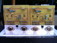
there is a picture of my version using far more advanced transistors from on semi mj 11015-16 but still ...at high rail voltage like 50+50 volts is trully unstable
plus the originall working at low voltage may be 40+40 volts is not stable at all as is
except all these very correct things that sixtec told you this is not working .....
i spend a year working with that playing here and there i managed to get 175w off it
but its extremelly unstable
there is a picture of my version using far more advanced transistors from on semi mj 11015-16 but still ...at high rail voltage like 50+50 volts is trully unstable
plus the originall working at low voltage may be 40+40 volts is not stable at all as is
Attachments
I have made it, and was dismounted as i did not have apreciated the sonics.
But i could fix the unstability problems.
Was dismounted as i do usually, to have parts to check other circuits..only 8 amplifiers had my respect and are assembled.
I have tried more than 4000 units.... they were in almost 36 groups of different schematics, with different circuitry.
Install a 18 picofarads capacitor in parallel with 22K resistance, the one at the feedback line....one side will go to the output line.
Install 470 to 680 picofarads capacitors into the output darlingtons, from colector to base.
Install a 47 picofarads capacitor into the TIP41, from base to colector.
It will work fine.....as i did that and worked for days without problems...the audio quality was the problem.
Suggested modifications were sent to Mr. Sakis...i have a copy of the mail sent to him.... he forgot that mail, or did not have received it.
regards,
Carlos
Just in case you didn't get the general consensus ....
Hi Gaetan
A good amplifier will include one or more of the following attributes;
- A stable constant current fed input stage.
- Well thought out gain stages (2nd and 3rd stages)
- Well thought out component choices for low noise, speed, reliability etc.
- A degree of symmetry so that the positive going signal is treated in a similar manner to the negative going signal.
- A clear and logically drawn schematic
- A clear and logically defined physical layout
This amplifier does not display any of these. I have seen this schematic around the internet for a long time now. Why anyone would bother to build it is beyond me. It would be cheap to make of course, but that saving will be lost very quickly when it fails and takes out more than you bargained for.
Have a look around DIY Audio, there are some excellent designs here that are not that much more complex but will perform to a good even excellent standard.
Cheers & Good Luck
Quasi
Re: I have made it, and was dismounted as i did not have apreciated the sonics.
Hi
You say that only 8 amplifiers had you respect and are assembled.
Please, can you tell me what are those amp where I can find those plans ?
Thank you
Gaetan
destroyer X said:But i could fix the unstability problems.
Was dismounted as i do usually, to have parts to check other circuits..only 8 amplifiers had my respect and are assembled.
I have tried more than 4000 units.... they were in almost 36 groups of different schematics, with different circuitry.
...
regards,
Carlos
Hi
You say that only 8 amplifiers had you respect and are assembled.
Please, can you tell me what are those amp where I can find those plans ?
Thank you
Gaetan
Re: Just in case you didn't get the general consensus ....
Hi
Is there a files section here in DIY audio where to find all of those excellent designs ?
If not, how about creating a files section with the best amp, preamp, and other best design. Because searching all messages here in DIY audio, without knowing which one have those best design, can be veryyyy long.
Thank
Gaetan
quasi said:Hi Gaetan
...
Have a look around DIY Audio, there are some excellent designs here that are not that much more complex but will perform to a good even excellent standard.
Cheers & Good Luck
Quasi
Hi
Is there a files section here in DIY audio where to find all of those excellent designs ?
If not, how about creating a files section with the best amp, preamp, and other best design. Because searching all messages here in DIY audio, without knowing which one have those best design, can be veryyyy long.
Thank
Gaetan
Hi
I should say a bit about me.
I'm not good in circuit design and analysing, I did somes amps and preamps kit, a 7294 amp and a lm3886 amp and some preamps. Those one chip amp are good but do have a bit lack of clarity in mid high and a lack of front-back space between voices and musical instruments.
I did compared them with a Sima and a Radford amps and a Dynaudio and a Spendor loudspeakers (there's friend systems).
Btw, I'm french speaking, so excuse my english.
Gaetan
OFFtopic
Sakis, please be patient, I will answer!
ONtopic
gaetan8888,
I have a design called ST151. That's a relative simple, short-circuit protected universal (sub, pa, hifi, guitar, etc....) audio power amplifier with easly-available and cheap parts, running with +/-40V and produces 100W-RMS. Stable and sounds good. I have full documentation (schematic, PCB, etc...)
Please tell me if you are interested.
Maybe I'm going to open a new thread for ST151?
sixtek said:
gaetan8888,
I have a design called ST151. That's a relative simple, short-circuit protected universal (sub, pa, hifi, guitar, etc....) audio power amplifier with easly-available and cheap parts, running with +/-40V and produces 100W-RMS. Stable and sounds good. I have full documentation (schematic, PCB, etc...)
Please tell me if you are interested.
Maybe I'm going to open a new thread for ST151?
Hey, sixtek, thats sounds very intresting, could you post your documents?
I do not feel happy to tell the ones are better, as people must discover those things
by themselves, doing tests, constructing...learning during practice..not believing in other folks words.
I think, giving you the receipt, i will not cooperate to your development if you believe me.....also i will be doing nothing, only beeing a clown telling you precious things that you may not follow.
Each one of us have a track to follow, our own destiny that will keep us distant from the ignorance.... it's a long way to go.
Just to suggest you some.
Try GEM, amplifier from Graham Maynard....it can be modified to work class AB...just reducing bias and removing some transistors..also he is able to give you a good follow up.
http://www.diyaudio.com/forums/showthread.php?postid=679236#post679236
Also you have mine Dx amplifier...more simple, made to be cheap, a little bit worst than GEM.... a small difference i mean with this " a little bit "
regards,
Carlos
sixtek said:OFFtopic
Sakis, please be patient, I will answer!
ONtopic
gaetan8888,
I have a design called ST151. That's a relative simple, short-circuit protected universal (sub, pa, hifi, guitar, etc....) audio power amplifier with easly-available and cheap parts, running with +/-40V and produces 100W-RMS. Stable and sounds good. I have full documentation (schematic, PCB, etc...)
Please tell me if you are interested.
Maybe I'm going to open a new thread for ST151?
Hi
Yes, open a new thread for ST151.
Thank
Gaetan
On a Russian website I found a complete article on this amplifier with 150 W TIP 142 and 147 output stage.
The .lay is available for download at the bottom of the page.
150 ???? ?? ???????????? TIP142 & TIP147
Good luck for the translation!
The .lay is available for download at the bottom of the page.
150 ???? ?? ???????????? TIP142 & TIP147
Good luck for the translation!
On a Russian website I found a complete article on this amplifier with 150 W TIP 142 and 147 output stage.
The .lay is available for download at the bottom of the page.
150 ???? ?? ???????????? TIP142 & TIP147
Good luck for the translation!
Language no problem, but no layout available.
Gets message that the material is copyrighted.

This amp does work, sort of, might do for a beginner because it's as simple as can be, but you'll spend the same and have a *real* amp if you build this one:
http://www.diyaudio.com/forums/solid-state/100907-st151-100w-amplifier.html
http://www.diyaudio.com/forums/solid-state/100907-st151-100w-amplifier.html
Hello
There is also the Dx amp from Carlos (destroyer X), easy to built and good sound.
http://www.diyaudio.com/forums/solid-state/96237-destroyer-x-amplifier-dx-amp-my-amplifier.html
Bye
Gaetan
There is also the Dx amp from Carlos (destroyer X), easy to built and good sound.
http://www.diyaudio.com/forums/solid-state/96237-destroyer-x-amplifier-dx-amp-my-amplifier.html
Bye
Gaetan
- Status
- This old topic is closed. If you want to reopen this topic, contact a moderator using the "Report Post" button.
- Home
- Amplifiers
- Solid State
- A 100-150 watt power amp using TIP41-142-147 transistors, how about