I have been testing my stochino amp that I built and never finished many years until recently when it was first published, and so far have destroyed a IRF9640 and a IRF640 mosfet transistor. I have been testing it using square and sine waves up 100khz the specs say the -3db power point is 120khz so it shouldnt have any problem with this. I was only drawing about 2.1 amps from recomended power supply and driving a 4.7ohm resistor load. The amp should deliver 120 watts into 8 ohms and probably more into 4.7ohms So there was plenty of capacity left. I was Luckily the mosfets did not destroy any of the eariler stages when they failed but its still annoying. The mosfets were faily well matched. Maybe I had a poor batch or that these are just poor and ill suited for this application. Has anyone had any similar experiences.
Steevo
Steevo
I don't think building a 120W/8R amplifier with a single pair of output devices is a good idea. And IRF640/IRFP9640 aren't an ideal choice, as TO220 devices can't dissipate very much heat.
You won't come even close to the 150 Watts the datasheet promises, no matter how big your heatsink is.
You won't come even close to the 150 Watts the datasheet promises, no matter how big your heatsink is.
The 1984 StoCChino* amplifier i recollect does state TO-220 devices, but has ~35Vdc rails.
The Stocchino 300V/uS design, printed in Electronics world in 1997, does 120W/8 but has 2 pairs of TO-220 irf640/irf9640
* CCh=k, Ch =g
(can't wait to read your lines on the DiS article, Holger. A shame the mag always arrives so late here)
The Stocchino 300V/uS design, printed in Electronics world in 1997, does 120W/8 but has 2 pairs of TO-220 irf640/irf9640
* CCh=k, Ch =g
(can't wait to read your lines on the DiS article, Holger. A shame the mag always arrives so late here)
I successfully built this amp several years ago and have been using them without problems since. The only issue I had was when first setting the bias current I didn't let the amp warm up enough and then wound the bias current up too much, which then caused a catastrophic failure. You only ever do that once...
Second time around worked like a charm. I'm pretty sure I ran a sine wave through the amp right up to 120W output (I used the higher 58V driver rail voltage) without any problems (but not at 100kHz). The power supply is regulated 55-58V for the driver stage and unregulated 48V for the output stage.
I have a question - why were you testing at 100KHz with >100W output? If you wanted to test the bandwidth, why not just run a watt or 2 through? From what I've read of other designs, few would stand up to such a test either.
Good luck - well worth fixing, as these are great sounding amps.
If the amp has been designed properly then it should full fill its specification as with any well designed and engineered piece of equipment. You dont buy a car that claims 0-60 in 7 secs only to find that it blows up if when you try it or instead of 7 secs you only get 8 seconds. I was simply testing it thoroughly cheking its performance.
Steevo
Steevo
Steevo
I understand what you are saying, but how long were you driving the amp at this power before they blew? John Atkinson from Stereophile tests all amps by driving them at 1/3rd of their rated power for an hour (within the audio bandwidth), which he describes as the worst case scenario for an amplifier. Most are too hot to touch and ones with thermal protection shutdown. So while amp specs say 100W into 8 ohm, you can't possibly drive a 20kHz square wave at full power for any extended period of time, unless you have huge heatsinking and/or fan forced cooling. How hot did the amp heatsinks get? Maybe they went into thermal overload?
I understand what you are saying, but how long were you driving the amp at this power before they blew? John Atkinson from Stereophile tests all amps by driving them at 1/3rd of their rated power for an hour (within the audio bandwidth), which he describes as the worst case scenario for an amplifier. Most are too hot to touch and ones with thermal protection shutdown. So while amp specs say 100W into 8 ohm, you can't possibly drive a 20kHz square wave at full power for any extended period of time, unless you have huge heatsinking and/or fan forced cooling. How hot did the amp heatsinks get? Maybe they went into thermal overload?
stochino
Hi,
IRFP640/9640 devices are not well suited for continuous high power application of that magnitude. Alex Soton reported problems with his Stochino amp running hot a few years ago on this forum. As I bought four boards of the amp as well we started to exchange ideas how to solve the problem.
Alex also intended to get rid of the NFB electros. It appeared that from the beginning both of us were somewhat suspicious about the use of IRFP640/9640 devices in this design. I suggested that IRFP240/9240 or SFH9240 devices would better dissipate heat.
Also the use of 2n5551/5401 input pairs created matching problems if the NFB electro was to be removed so we decided to use 2sa970bl/2sc2240bl instead. Alex managed to match their hfe within 1%, my batch allowed me to match them within 2-5%.
Anyway, after Alex IRFP640/9640s blew he increased gate resistors to 100ohm and used IRFP240/9240 pairs and all problems disappeared. The amp with 150mA bias was running cool, while before he could not go above 120mA.
As I had a few other more urgent things to do my boards still miss a few parts and amps are not yet running. Running the amp without NFB caps was less successful. Offset in one of his amps was almost acceptable at about 40-60mV but the other channel was above 250mV. I do not know if he has managed to fix that problem since then as he also had a few other things to do apart from experimenting with offset.
Most of his experience with Stochino amp is available on his site
www. soton.ac.uk
cheers,
Hi Janusz
I saw on another post that you (or maybe is was someone else on the thread) was looking at a way of matching devices. Have you seen the Elektor circuit (Giesberts) for the power mosfet matcher? I am constructing this at the moment. It tests 2 x N channel and 2x P channel at the same time. Was published in Nov 93 issue.
Can you also tell me the link to Alex Soton's site?
Thanks
stochino
Hi Smithy,
Alex'es site is
www.soton.ac.uk
It's the addres I gave in the previous post but without that space.
Yes, some time ago I was looking for a good circuit to match Mosfets. I got one used by Nelson Pass, one from ESP and some other one. I did not see the one from Elektor so I'd be grateful if you could send me a scan of this circuit with some description. It sounds interesting.
my direct email is:
janusz.pradzynski@dpi.wa.gov.au
I hoped to have my first two Stochino modules finished by the New Year but first I had to fix my Yamaha c-65 preamp I bought on Ebay last year. It took me some time to fix all problems and when assemblig somehow I shortcircuited two resistors which were soldered vertically. If they were soldered with theother ends down nothing would have happened but in this case two emitters were shortcircuited and smal part of the board damaged by burning transistor. Hope to fix it this weekend. That will be no problem if the input transistors are still OK.
cheers,
Hi Janusz
I've sent through a pdf of the mosfet tester circuit. I should have mine finished in a couple fo weeks so I'll let you know how it goes.
I'm also finishing some new cases for my Stochinno amps - the old ones are in 19" rack mount, but I've built from scratch some custom aluminium boxes (don't do it - hundreds of hours of work), which I am going to get anodised in a funky colour. So I'll be moving my modules over to the new boxes soon.
Let me know how you get on with the amp modules.
I only ran the amp for a few seconds at that level and frequency with which I stated and it was not at full power.
I am going to make sure the mosfets are screwed tight down and have good thermal contact with the heat sink just incase that was an issue. The others survived.
I would expect to run the amp for a few mins assuming the temperature allowed it which it does. I have a big 0.7 deg/watt heatsink for each channel.
Moderators,
You would do well to change the name of the thread to the correct spelling of the original author. This will help when people do a search on the web in general and in this forum specifically.
Well, I have built several Stochino boards and tested them successfully. I have had no issues so far. However, I only completed one two channel amplifier, running +-55 volts for the front end (regulated) and +-48 volts for the output stage (unregulated). The output devices were IRF9640 and 640. I was not aware of matching issues about 5-7 years ago and I do not know how close they were.
The offset I got consistently from every board was in the range of 33-35mV despite tight matching of all other components including passive devices.
The difference was that I used BAW62 diodes instead of the specified IN4448 ones and I also soldered the TL431 on the track side and inserted this into a 5mm hole in the heatsink filled with heatsink compound. I never notices any thermal drift or problems with Iq. Ofcourse, the PCBs were my own design (hand painted and etched). I also used a pair of series connected IN4148s in anti-parallel with the DC blocking cap in the feedback network. The cap itself was again a bipolar made up with two 330uF caps.
Since this amp has a very high GBW, PCB layout and parasitics will play a huge role in stability.
I have no idea of the current state of the finished amp since I have lost contact with the friend for who it was made.
Perhaps, in a week or two I should have another amp or two ready and I will post some pictures, now that I have a fairly good quality Digital Camera.
As for the sound, this is the best I have heard thus far and I guess only Nelson's F4 might better it. The latter is my next project and I am only looking for the input JFETs.
Hope this raises hopes for the ones who are trying out the fantastic amp.
stochino amp
Hi Sam,
Glad to hear from you again. Looks that the boards of your design might be somewhat better than those sold by EW.
I have decided to run the amp from +/-57V so IRFP240/9240s were my first choice. With the NFB cap in and matched 2sa/2sc trnasistors Alex pushed the offset below 10mV. Only without the NFB cap it was high. Alex did not use 1n4448 diodes but bax16.
cheers,
Samuel Jayaraj said:change the name of the thread to the correct spelling of the original author.
Sam,
you took the words right out of my mouth.
A bit embarassing imo that someone with so many audio related patents on his name and who has contributed so many times to Electronics World hasn't earned to have his name spelled right.
A link to both the high slewrate Stocchino amp schematic and the ones for the (regulated) powersupplies :
www.angelfire.com/sd/paulkemble/sound8c.html
Collectors item, there's also a schematic of one of the earliest Hitachi lateral MOSFET power amp designs on Paul Kemble's place : the output stage of the HA-7700 from 1979 =>
Attachments
steevo said:I only ran the amp for a few seconds at that level and frequency with which I stated and it was not at full power.
I am going to make sure the mosfets are screwed tight down and have good thermal contact with the heat sink just incase that was an issue. The others survived.
I would expect to run the amp for a few mins assuming the temperature allowed it which it does. I have a big 0.7 deg/watt heatsink for each channel.
Steevo
Did you have it working ok before you ran 100k through it? Was it working ok at 1kHz at full power? I ran my modules at full power at 1kHz with no problem. Sorry if I am insulting you by asking, but I assume you had succesfully set the bias current on this module already and particularly after warmup?
Once I was playing with an amp I made with a 100KHz square wave and sines of such frequencies and I noticed the output transistors were cross-conducting and large currents were flowing due to EF AB bias at high frequencies. I placed a 100uF cap from one base to the other, and alleviated the problem. The drivers in darlington also required such a fix, but only 10uF. Problem is the output capacitance of the transistor requires current to turn the device off at higher speeds before the other turns on. The cap allowed the negative driver to turn off the positive output, and visa versa by supplying an AC current path accross the DC bias. This was with 20MHz BJT's but the same problem exists with mosfets, in spades. Certainly if I removed the cap, the outputs would have released smoke if sustained 200KHz full power output because of overbias.
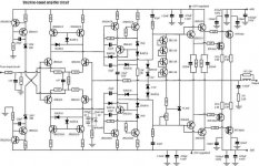
If anyone is interested here is the final circuit I used, I had to reduce it 1000 X 1000 pixels so some details is lost. I have the complete power amp article scanned in as JPG images and both sides of the PCB scanned in high resolution. If anyone wishes I can email them the complete article circuit diagram and PCB images.
Attachments
Hi,
my rule for predicting maximum output power from an output stage into a reactive (speaker) load is max Pout<=total device Pd/6.
your 2pair of 640/9640 have about total capacity of 480W. This would indicate 80W into a severe speaker load.
+-48Vdc rails and 8ohm load should give about this level of output.
I use a second, but usually less demanding, rule the output voltage into half load RESISTANCE should be about -0.5db. i.e. 80Winto 8ohm becomes 140W to 150W into 4r0. (or 136W into 4r7 @ -0db).
Both these tests MUST be done with the heatsink at normal operating temperatures. This usually means testing for just a second or so to get the scope view and then on the next run get the unclipped voltage readings (upto 20kHz). If you want to blow up an amp then the best way is sustained power into low loads with the heatsink temperature rising way above design temperature.
BTW. 0.7C/W is a medium rated, but adequate sink for domestic listening, IF the output bias is kept low. A FET amp demands high bias and as a result demands a big sink.
- Status
- This old topic is closed. If you want to reopen this topic, contact a moderator using the "Report Post" button.
- Home
- Amplifiers
- Solid State
- Giovanni Stochino Power Amp