Hi everybody,
This is my first aproach to this forum.
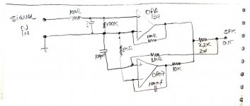
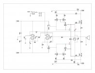
I piked up this circuit from an amplifier of a friend of mine(it sounds great !!!).
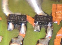
I would like to know the value of each the three marked components (because they are SMD).
What do you think about this design?
I wish to duplicate this amplifier.
Is the data OK?
Thanks to everybody.
Best regards.
Braco
This is my first aproach to this forum.
I piked up this circuit from an amplifier of a friend of mine(it sounds great !!!).
I would like to know the value of each the three marked components (because they are SMD).
What do you think about this design?
I wish to duplicate this amplifier.
Is the data OK?
Thanks to everybody.
Best regards.
Braco
Attachments
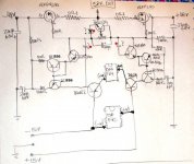
Base of MJE350 is missing a connection, should be a mirror image of what is going on with MJE340.
The ?marked diode can be an industry standard 1n4148 or similar, I guess it sould be not on heatsink while bd139 should be on heatsink.
The ?marked capacitors is a hard question, try asking your friend, I can estimate they are in 10p-150pF range.
Generally I think this amplifier can be good with high bias current of output mosfets (>150mA), current of op-amps is charging mosfets' gates which is not very nice together with low bias.
Have fun DIYing!!
regards
Adam
Hi Adam,
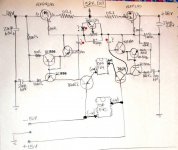
you are right with the base connection of the MJE350, here is the correction.
You are right too with the BD139 he is on heatsink.
Thanks with thd diode code, sorry with my english and I'm rookie in electronics, thats why I am asking for help.
Here is the correction on the schema
Cheers
Braco
you are right with the base connection of the MJE350, here is the correction.
You are right too with the BD139 he is on heatsink.
Thanks with thd diode code, sorry with my english and I'm rookie in electronics, thats why I am asking for help.
Here is the correction on the schema
Cheers
Braco
Attachments
Hi Braco,
A question about identifying SMD transistors came up in another thread recently and a very helpful member supplied the link below. It's a large table in PDF format, sorted by package marker numbers with corresponding device number, manufacturer, pin-out and the leaded-equivalent device info.
http://www.kipa-bg.com/html/SMD_CODS.pdf
I have yet to use the table, so I can guarantee its accuracy!
Nice one,
David.
A few weeks ago I posted this treath with 3 pictures, well here is the complete schema in one piece.
Would you be so nice to criticize thewholecircuit. Remember I'm rookie in electronics.
Thanks in advance
PS: sorry it's my first time with Express SCH.
Would you be so nice to criticize thewholecircuit. Remember I'm rookie in electronics.
Thanks in advance
PS: sorry it's my first time with Express SCH.
Attachments
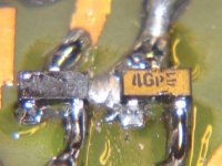
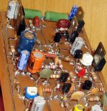
Finally i see people constructing this way
Soldering parts over the copper foil board.
I do this way since the sixties.
Better to see this late than never.
Sorry the fast off topic, but it is not easy to find people doing this way.
I am not lonely anymore
regards,
Carlos
Soldering parts over the copper foil board.
I do this way since the sixties.
Better to see this late than never.
Sorry the fast off topic, but it is not easy to find people doing this way.
I am not lonely anymore
regards,
Carlos
Attachments

- Status
- This old topic is closed. If you want to reopen this topic, contact a moderator using the "Report Post" button.
- Home
- Amplifiers
- Solid State
- NEW schematic layout