Distortion in Circuitmaker 2000
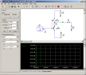
Select Analog Mode in Simulation, then go to Analyses Setup (F8), enable Transient/Fourier analysis and click on that button. In Transient and Fourier Analysis Setup enable Fourier (check box). At this moment I have the default timing selected (5 cycles, 50 points per cycle). Use a sine generator in the circuit diagram as input, e.g. at 1 kHz. Probe the output, or any point in the circuit.
Default the fourier analysis shows a linear frequency scale as the X-axis and volts or amps on the Y-axis. Right click on the Y-axis to get a pop up where you can select Primary Y-axis with Magnitude in Decibels. Then adjust the scaling, normally in the left pane, to e.g. 20dB per division and adjust the offset to get the harmonics in the graph. Distortion is calculated from the ratio of the harmonics and the fundamental.
Attachments
bogdan_borko said:how did you calculated 0.1%?
Hi,
0.1% is a thousanth = 10 to the power - 3 x 20 = - 60dB.
From the graph 2nd and 3rd dominate so I'd say ~ 0.2%.
") /sreten.
/sreten.
Hi,
THD is simply the linear sum of the harmonics + noise compared to the signal.
So one amplifier could have 5% THD consisting mainly of 2nd harmonic.
Another could have 5% spread evenly across the harmonics up to 20K.
The second will sound very much worse than the first.
The formula I gave is a way of weighting harmonics to more accurately
reflect their impairment of sound quality. It shows why a valve amplifier
with 3% distortion could sound nicer than a transistor amplifier with 0.5%.
Weighting is not popular as it always increases the quoted distortion figure.
Weighting is popular when it improves the quoted figures,
for example A-weighted rumble figures for turntables.
/sreten.
THD is simply the linear sum of the harmonics + noise compared to the signal.
So one amplifier could have 5% THD consisting mainly of 2nd harmonic.
Another could have 5% spread evenly across the harmonics up to 20K.
The second will sound very much worse than the first.
The formula I gave is a way of weighting harmonics to more accurately
reflect their impairment of sound quality. It shows why a valve amplifier
with 3% distortion could sound nicer than a transistor amplifier with 0.5%.
Weighting is not popular as it always increases the quoted distortion figure.
Weighting is popular when it improves the quoted figures,
for example A-weighted rumble figures for turntables.
/sreten.How to calculate harmonic distortion
Just to make the calculations a bit more clear:
In the shown graph the fundamental has a level of 30dB, the 2nd harmonic is -40dB, 3rd also -40dB, 4th is -56dB, 5th also -56dB, etc.
If we normalise the fundamental to 0dB, then the 2nd harmonic is 70dB below the fundamental, so at -70dB, 3rd at -70dB, 4th at -86dB, 5th at -86dB, 6th ~ 9th at -100dB.
For calculation of the THD it is easy to go back to real values instead of dBs. The fundamental is 0dB = 1, the 2nd harmonic is -70dB = 10^(-70/20) = 3.16E-4, 3rd also 3.16E-4, 4th is -86dB = 10^(-86/20) = 5.01E-5, 5th also, 6th ~9th harmonic is -100dB = 1E-5.
Total harmonic distortion (THD) is the square root taken from the sum of the harmonics squared, divided by the fundamental.
THD = SQRT((3.16E-4)^2) + (3.16E-4)^2 + (5.01E-5)^2 + (5.01E-5)^2 + (1E-5)^2 + ...)/1 = 4.53E-4 = 0.045%
Weighted harmonic distortion (WTHD) takes into account that higher harmonics are more annoying than lower oder harmonics. Shorter proposed in 1950 the n^2/4 rule, with n is the number of the harmonic. So 2nd harmonic is multiplied by 1, the 3rd by 9/4, et cetera. After weighing of the harmonics, the WTHD is calculated in the same manner as the THD. In the above case the WTHD is 9.13E-4 = 0.091%. This is not much worse than the unweighted THD because higher harmonics are very low in this example. If e.g. the 9th ahrmonic would have had the same value as the 2nd, then the WTHD would have been 0.65% already.
thank you steven.
I know that 2th harmonic sounds "good", 3rd is "sharp"
and 5th is "bad" becouse is apsolutly out of tune...
but I`d like to know what I must have in mind about harmonics when I design an amplifier stage, what level of what harmonic is unacceptable, what is the "best" level difference between 2nd and 3rd harmonic....
Some reading about harmonic distortion and audibility:
A NEW METHODOLOGY FOR AUDIO FREQUENCY POWER AMPLIFIER TESTING BASED ON PSYCHOACOUSTIC DATA THAT BETTER CORRELATES WITH SOUND QUALITY
(Thesis form Daniel H. Cheever)
It can be downloaded here: http://w3.mit.edu/cheever/www/cheever_thesis.pdf
Small-Signal Distortion in Feedback Amplifiers for Audio
by James Boyk and Gerald Jay Sussman
It can be downloaded here: http://www.its.caltech.edu/~musiclab/feedback-paper-acrobat.pdf
Don't read Cheever's thesis - he abuses too many concepts and will leave your understanding of the subject in negative territory - you will have to "unlearn" almost anything you think you've understood from Cheever
please Don't recomend Cheever to anyone - especially someone without experience and background
please Don't recomend Cheever to anyone - especially someone without experience and background
jcx said:Don't read Cheever's thesis - he abuses too many concepts and will leave your understanding of the subject in negative territory - you will have to "unlearn" almost anything you think you've understood from Cheever
please Don't recomend Cheever to anyone - especially someone without experience and background
Hi,
I found the first chapter a good overview.
The second chapter - fairly pointless.
/sreten.Import from P-Spice Parameter of new devices (Text files)
need a little help for follow task: the import of P-Spice parameters from new BjT power devices - e. g. Onsemi's MJL4281:
ON Semiconductor
in the instruction manual (Chapter 9) I read only this:
Import > Simulate Spice Netlist
Use this option to import and simulate a Spice netlist that you might have created in another simulation program. When you use this feature, CircuitMaker does not display the actual schematic drawing. Instead, it runs the simulation, displays the analysis window, and places a Waveforms list at the bottom of the Panel which you can use to choose different variables to plot. SVGA display is a minimum requirement to access the Waveforms list. See Figure 9.1 in the user manual about
http://www.gel.usherbrooke.ca/ste/ste/pcb/cm_usermanual.pdf
But about the import for new models I don't find the appropriate chapter
What is the right way?
- Status
- This old topic is closed. If you want to reopen this topic, contact a moderator using the "Report Post" button.
- Home
- Design & Build
- Software Tools
- Circuit Maker <<questions>>