Hi everyone,
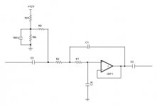
I tried to make a simple 12db/octave active lowpass filter, using the schematic found on WinISD - see picture attached.
However, all it gives is buzz on the output. No 'magic smoke' however.
Details:
op-amp - one side of JRC-2114 (also called NJM-2114 I think)
+ and - 13v unregulated psu (for the purposes of testing)
polyester .33uF caps and 1/4w carbon resistors, 10k
soldered on veroboard
100uF low-z psu bypass on the veroboard
Tested from CD player output (unmodified 1990s Rotel) and fed into subwoofer plate amp (RCM Acustik DT 110 MK II). (CD player direct to sub works fine)
Have I most likely made a wiring mistake? Or is this op-amp not suitable for this application? Anything sound dodgy?
I will recheck when I get home from work, and take photos as close-up as I can.
Attachments
I think your problem lies in that the non-inverting input has no DC path to ground if your CD player has a capacitor in the output (which it 99.99% will have). Place a 10k-100k resistor from your filter input point to ground.
I can't say if those op-amps are unity gain stable or not as they are not common ones. Get some proper ones from Bardwell's") Also bear in mind that the unused op-amp in the package may well be doing all sorts of strange things if the inputs are not connected to anything, and it is likely to affect the used op-amp. Simply connect the unused op-amp as a unity gain buffer and ground the non-inverting input.
Also bear in mind that the unused op-amp in the package may well be doing all sorts of strange things if the inputs are not connected to anything, and it is likely to affect the used op-amp. Simply connect the unused op-amp as a unity gain buffer and ground the non-inverting input.
I can't say if those op-amps are unity gain stable or not as they are not common ones. Get some proper ones from Bardwell's
Also bear in mind that the unused op-amp in the package may well be doing all sorts of strange things if the inputs are not connected to anything, and it is likely to affect the used op-amp. Simply connect the unused op-amp as a unity gain buffer and ground the non-inverting input.I trust that the OP-amp, for DC would be a voltage follower, and that the GND is just not shown. Basically, it looks like 2 LP filters in series, and then fed to a OP-amp follower/****** stage.
Nothing fancy there.
Check for (the obvious) solder-mistakes, and then check for shorted caps or resistors.
If either of the caps is shorted, you won't get meaningful signal through it.
Jennice
Nothing fancy there.
Check for (the obvious) solder-mistakes, and then check for shorted caps or resistors.
If either of the caps is shorted, you won't get meaningful signal through it.
Jennice
Thanks for the replies guys!
I suspected I'd not done enough with the ground.
Secondly, he probably has more stuff in stock than Maplin!
Thirdly, the op-amp is one I pulled out of my main cd player - CD63ki (a victim of 'upgrade' - to 2604).
http://www.njr.co.jp/pdf/ae/ae04028.pdf
Fourthly, I don't know what a unity gain buffer is. My understanding of electronics is 'beginner-level' at best.
Jennice, I will check for shorts carefully.
As the op-amp is just being recycled (and this is an experiment frankly, to feed my sub a 24db/oct cut-off from ~50hz) I don't mind too much if I have to buy one. The UA741 mentioned in the schematic, is that about the most common effort going?
Thanks for taking the time to help me. I'm eager to hear my sub crossed over more appropriately...
I suspected I'd not done enough with the ground.
This will be the first thing I try when I get home!richie00boy said:I think your problem lies in that the non-inverting input has no DC path to ground if your CD player has a capacitor in the output (which it 99.99% will have). Place a 10k-100k resistor from your filter input point to ground.
Firstly, Bardwell never has anything! heheI can't say if those op-amps are unity gain stable or not as they are not common ones. Get some proper ones from Bardwell's
Secondly, he probably has more stuff in stock than Maplin!
Thirdly, the op-amp is one I pulled out of my main cd player - CD63ki (a victim of 'upgrade' - to 2604).
http://www.njr.co.jp/pdf/ae/ae04028.pdf
Fourthly, I don't know what a unity gain buffer is. My understanding of electronics is 'beginner-level' at best.
Jennice, I will check for shorts carefully.
As the op-amp is just being recycled (and this is an experiment frankly, to feed my sub a 24db/oct cut-off from ~50hz) I don't mind too much if I have to buy one. The UA741 mentioned in the schematic, is that about the most common effort going?
Thanks for taking the time to help me. I'm eager to hear my sub crossed over more appropriately...
Bardwell's is OK as you as your aren't after namby pamby esoteric nonsense
I'm sure my tip with the input resistor will fix it and, if it doesn't and the assembly is OK as per Jennice's recommendation, then correctly terminating the unused op-amp will probably solve it. A unity gain buffer is simply a buffer with a gain of 1. All you need to do is connect the inverting input to output (thus 100% negative feedback) and the signal (ground in this particular case) goes to the non-inverting input. Couldn't be simpler.
A 741 will do and is 'the' generic op-amp, but I'm sure Bardwells will sell you a TL071 (single) or TL072 (dual) which will be infinitely better. An NE5534 will not be suitable in this case without an additional capacitor for compensation, but the dual version -- NE5532 -- will be fine.
Just an additional remark:
As soon as your circuit is working you might find it a little noisy: In this case think about using smaller resistors like 10 k and use larger caps instead.
As far as your hum goes: I also expect it to come from a wiring error or ground loop (how does your DC suplly voltage look like BTW ?).
Another remark to your crossover: This is a subtractive-type crossover (which is transient-perfect or phase_accurate BTW !!) that generates a first-order highpass function by subtracting a lowpass from the input signal. This highpass has a hump due to mathematical reasons (this is NOT a hump caused by a high-Q pole, causing ringing !) that is depending on the lowpass' Q. If you use a filter of lower Q then the hump will be smaller. Many people use a Bessel 2nd-order lowpass for this reason (yours is a Butterworth one).
Regards
Charles
Namby pamby esoteric nonsense? Me?richie00boy said:Bardwell's is OK as you as your aren't after namby pamby esoteric nonsense
I'm sure my tip with the input resistor will fix it and, if it doesn't and the assembly is OK as per Jennice's recommendation, then correctly terminating the unused op-amp will probably solve it. A unity gain buffer is simply a buffer with a gain of 1. All you need to do is connect the inverting input to output (thus 100% negative feedback) and the signal (ground in this particular case) goes to the non-inverting input. Couldn't be simpler.
A 741 will do and is 'the' generic op-amp, but I'm sure Bardwells will sell you a TL071 (single) or TL072 (dual) which will be infinitely better. An NE5534 will not be suitable in this case without an additional capacitor for compensation, but the dual version -- NE5532 -- will be fine.

Thanks for the unity gain buffer explanation, it seems quite clear-cut. "As clear as an un-muddied lake, sir." In truth, I might get back to you on it, but only if needs be!
Interesting you should mention the NE5532 - I think the op-amp I'm using is very similar (read that somewhere). I'm sure I could still produce magic smoke, and if I do Bardwell's is 5mins drive, as I recall I told you once before
Look at this!
Everything explained very well.
http://kahuna.sdsu.edu/~tucker/diyaudio/xover.html
Regards
Everything explained very well.
http://kahuna.sdsu.edu/~tucker/diyaudio/xover.html
Regards
I appreciate remarks. But did you perhaps make a mistake in saying '10k'? I am using 10kphase_accurate said:Just an additional remark:
As soon as your circuit is working you might find it a little noisy: In this case think about using smaller resistors like 10 k and use larger caps instead.
As far as your hum goes: I also expect it to come from a wiring error or ground loop (how does your DC suplly voltage look like BTW ?).

I only plugged this thing in at 12.30am and really had to go to bed, or else I'd have multimetered things a bit more, like the output. My DC supply is about 13 volts, unregulated. I am mixing it's 'ground' with the input and output grounds. Should I be concerned by my lack of regulation? If this ever works I will add some 3-pin regulators into the mix.
I'd like to pose another electronics question in if I may. Does it matter what I 'drive' this circuit from? The signal will ultimately want to come from either the volume pot of my passive chip-amp or my Roksan Caspian pre-out (not sure which really sounds better, but I know which I can sell on Ebay!).
Maybe I have to see an optician, but I could bet almost every resistor on the shematic that you posted is 100 k.
Is your supply symmetrical like +- 13 Volts and not just 13 Volts ?
The source driving your circuit does indeed matter but not to the extent that it should cause a go/no-go situation. It will rather influence quality.
I couldn't find any datasheet on this op-amp but I'd like to know whether this op-amp is unity-gain stable or not (a prerequisite for this circuit).
Regards
Charles
I think Charles slightly confused matters by talking not about your circuit SimontY, but Dave's (planet10).
If you are going to drive your circuit you will need a buffer before the filter as your passive attenuator will screw things up with it's poor impedance characteristics. I'd be willing to bet also that the pre-outs on your Roksan thingy are not buffered terribly well, if at all, so again you will need a buffer.
If you are going to drive your circuit you will need a buffer before the filter as your passive attenuator will screw things up with it's poor impedance characteristics. I'd be willing to bet also that the pre-outs on your Roksan thingy are not buffered terribly well, if at all, so again you will need a buffer.
Reading it now, very useful. Cheers.klitgt said:Look at this!
Everything explained very well.
http://kahuna.sdsu.edu/~tucker/diyaudio/xover.html
Regards
Yikes, it's getting hard to keep up!
phase_accurate
"I could bet almost every resistor on the shematic that you posted is 100 k"
richie00boy
"I think Charles slightly confused matters by talking not about your circuit SimontY, but Dave's (planet10)"
Yes, that's what happened, oops! I'll assume my values are fine for now then.
"If you are going to drive your circuit you will need a buffer before the filter as your passive attenuator will screw things up with it's poor impedance characteristics."
Ok, I will try to consider this more fully once I have this circuit functioning. This will all come in very handy when finishing off my friend's basement floor shaker (it shakes, but it's not quite right yet...)
Ouroboros
"You are running the op-amp on +/- split supplies aren't you?"
Yes, I am using a toroid with 2x 9vac secondaries, with a bridge rectifier on each, connected at the middle, to give + and -. I believe I have this part correct, as I did the same for my experimental chip amp (this split thing confused the HECK out of me at first). Haha, and when making our floorshaker we blew up a 6,800uF. Couldn't stop laughing, I think that smelly steaming electrolyte acts as laughing gas or something!!! I test with goggles now...
phase_accurate
"I could bet almost every resistor on the shematic that you posted is 100 k"
richie00boy
"I think Charles slightly confused matters by talking not about your circuit SimontY, but Dave's (planet10)"
Yes, that's what happened, oops! I'll assume my values are fine for now then.
"If you are going to drive your circuit you will need a buffer before the filter as your passive attenuator will screw things up with it's poor impedance characteristics."
Ok, I will try to consider this more fully once I have this circuit functioning. This will all come in very handy when finishing off my friend's basement floor shaker (it shakes, but it's not quite right yet...)Ouroboros
"You are running the op-amp on +/- split supplies aren't you?"
Yes, I am using a toroid with 2x 9vac secondaries, with a bridge rectifier on each, connected at the middle, to give + and -. I believe I have this part correct, as I did the same for my experimental chip amp (this split thing confused the HECK out of me at first). Haha, and when making our floorshaker we blew up a 6,800uF. Couldn't stop laughing, I think that smelly steaming electrolyte acts as laughing gas or something!!! I test with goggles now...
Thanks, I did realise this was possible. I saw a similar circuit here:Ouroboros said:You could run on a single rail like this, but equal split-supplies are best.
http://focus.ti.com/lit/an/sloa093/sloa093.pdf
However, I would find it hard to believe it could sound great going through two additional capacitors. Psychologicaly it would be a problem at least, but luckily one day I decided on a whim to buy this transformer through Ebay...
Thanks Jennice, it's downloading right now.Jennice said:Simon,
I've had some trouble with my ftp server, but try to see if you can get my PDF file with some notes on DIY audio. (address in the tag line below). There's a section on OP-Amps in it.
Jennice
Good evening everyone,
I'm home now and have had another look at my circuit.
I measured the full AC psu voltage on the output: ~27vac
So I proceded to connect a 22k resistor from input to ground, as per suggestions. This took away the AC but I was left with 5vdc!
I tested this anyway, and buried deep within the hum/buz was the music signal!
Next step - I joined pins 6 and 7 together (B-IN >> B OUTPUT), as per richie00boy's advice, and pin 5 (B+IN) I connected to ground. This took me back to having the full AC voltage on the output.
I have carefully checked my connections and to my untrained eye everything looks fine. I checked for continuity in many places and found no shorts. Power - and + go to the correct pins. Where the signal goes in appears to go through the two resistors, and the caps appear to be in the correct positions.
One thing I wonder about - where the schematic shows the output being directly connected to -INPUT --is this really just a plain short?? That is how I have connected it.
If there are no obvious mistakes remaining I think I will just pack it in and buy the correct (single) op-amp. Not like it's costing me very much money.
- Status
- This old topic is closed. If you want to reopen this topic, contact a moderator using the "Report Post" button.
- Home
- Design & Build
- Software Tools
- 1st attempt of 2nd order active lowpass filter failed, please advise