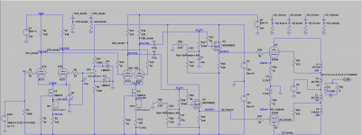
Any suggestions how I can improve the performance of the sim or the circuit?
Let's not call it improvement but another solution.
Disconnect the G2's from the UL tap and give them a separate regulated supply (that one you use for the 6CG7's). Remember that if the CFb is 24% then your actual UL ratio becomes 24+33=56% when CFb is on.
If you disconnect the G2's it will become 24% (modified) ultra-linear. Then disconnect the 27K anode resistors of the 6CG7's from the 505V supply and connect them to the UL tap in cross-coupled fashion (where you get 505V as well minus a few volts for the UL tap DC resistance). This way you will bootstrap the 27K anode resistors (i.e. will multiply their AC value = more swing with less distortion).
Because the UL ratio is less (i.e. closer to pentode) you might get even more power.
P.S.
I have just noticed that you are not using 24% CFb.
So the ratios will be according to the actual transformer you are easing but the idea is the same....
P.P.S.
If you are using the VDV4070 with 5 ohm load you can do the same with the Polish 4K when you use 24% CFb to get the same primary load.
In fact the VDV has 28.267:1 turn ratio without CFb. It becomes 30.437 in total when CFb at 7.1% is connected. So for 5R this is 4.63K.
The Polish OT is 22.36:1 without CFb. This becomes 29.431 with 24% CFb. That's about the same.....
Before you changing anything, look at output tube G1 waveform in the simulator.
About +30V.... -150V swing.
Then look in 6550 datasheet the UL characteristic: 0V... -70V swing.
No comment.
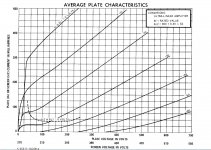
Hi. I have Tung-Sol and Eletro-Harmonix datasheets but I can't find that specification in either. The EH datasheet has no charts at all.
There are some typical UL operating characteristics I am exceeding:
Plate and grid 2 voltage DC: 450V
Grid 1 Voltage DC: -48V
Maximum signal power output: 70W
but these are just "typical".
Let's not call it improvement but another solution.
Disconnect the G2's from the UL tap and give them a separate regulated supply (that one you use for the 6CG7's). Remember that if the CFb is 24% then your actual UL ratio becomes 24+33=56% when CFb is on.
If you disconnect the G2's it will become 24% (modified) ultra-linear. Then disconnect the 27K anode resistors of the 6CG7's from the 505V supply and connect them to the UL tap in cross-coupled fashion (where you get 505V as well minus a few volts for the UL tap DC resistance). This way you will bootstrap the 27K anode resistors (i.e. will multiply their AC value = more swing with less distortion).
Because the UL ratio is less (i.e. closer to pentode) you might get even more power.
Thanks 45. I'll sim this too.
Hi. I have Tung-Sol and Eletro-Harmonix datasheets but I can't find that specification in either.
GE 6550-A
electron Tube Data sheets - 6
Attachments
Thanks. I have that datasheet too but didn't look too deeply because it's a 6550A. Looks the same as the 6550 though.
The negative swing beyond -70V is a result of the cathode feedback. Seems to work in the simulation anyway.
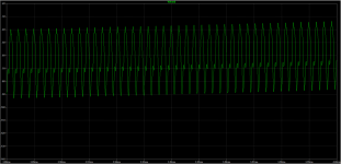
Try to increase K factor from 0.9995 to 0.99995, as you probably have too much leakage inductance as shown by the ringing top waveform, esp. at higher output.
According to Using Transformers in LTspice/Switcher CAD III
Lleak = L * (1 - K**2)
For the VDV transformer, L = 813H and Lleak = 2.55mH.
This gives K = 0.999998.
Let's not call it improvement but another solution.
Disconnect the G2's from the UL tap and give them a separate regulated supply (that one you use for the 6CG7's). Remember that if the CFb is 24% then your actual UL ratio becomes 24+33=56% when CFb is on.
If you disconnect the G2's it will become 24% (modified) ultra-linear. Then disconnect the 27K anode resistors of the 6CG7's from the 505V supply and connect them to the UL tap in cross-coupled fashion (where you get 505V as well minus a few volts for the UL tap DC resistance). This way you will bootstrap the 27K anode resistors (i.e. will multiply their AC value = more swing with less distortion).
Because the UL ratio is less (i.e. closer to pentode) you might get even more power.
Hi,
I rearranged the sim as suggested but it oscillates. Any suggestions for fixing that please?
Thanks.
Attachments
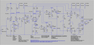
A 3k + 470p zobel network from primary centre tap (B+) to each anode will get rid of the oscillations. I can't re-post the .asc file as I had to change a few things to make it work with my LTspice setup.
Gives about 5dB of NFB but distortion seems to get worse.
Other parts of your simulation - you could just ground R1 and R8 and get rid of R9,10,11, IC3, IC4, and C1. Also R14/R12 could be grounded to reduce dissipation in IC2.
Gives about 5dB of NFB but distortion seems to get worse.
Other parts of your simulation - you could just ground R1 and R8 and get rid of R9,10,11, IC3, IC4, and C1. Also R14/R12 could be grounded to reduce dissipation in IC2.
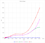
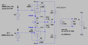
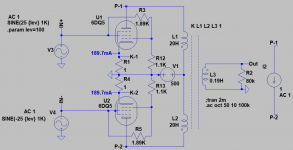
Transformer/cathode feedback comparison
I thought I should complete this thread with a summary of my findings with the VDV4070CFB transformer.
Firstly, I found a much better operating point for the second LTP. Turns out that increasing the LTP anodes increases THD from the stage but reduces output THD.
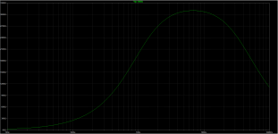
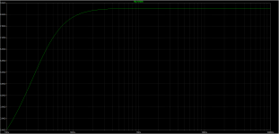
Sim schematic is attached along with a full chart and a 10W chart showing:
The UDB performs ~0.15% THD better than the Williamson but max power is the same.
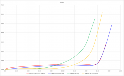
I thought I should complete this thread with a summary of my findings with the VDV4070CFB transformer.
Firstly, I found a much better operating point for the second LTP. Turns out that increasing the LTP anodes increases THD from the stage but reduces output THD.
Sim schematic is attached along with a full chart and a 10W chart showing:
- Universal Driver Board (UDB) and VDV4070CFB transformer
- UDB and VDV4070CFB transformer with 4dB of global feedback
- UDB and Hammond 1650R 5K transformer (thanks to SPICE Transformer Model Spreadsheet I had a good model for this)
- A Williamson amp I built a couple of years ago driving the same transformer (also with 505V HT)
The UDB performs ~0.15% THD better than the Williamson but max power is the same.
Attachments
Thanks. Is this what you had in mind and did you get a similar result?
Yes, and yes
") . The E-linear feedback results in increased distortion in the second LTP, the loadline steepens. I increased the load resistors from 27k to 47k and increased the ccs current to 8mA but the LTP runs out of current swing before the output stage clips.
. The E-linear feedback results in increased distortion in the second LTP, the loadline steepens. I increased the load resistors from 27k to 47k and increased the ccs current to 8mA but the LTP runs out of current swing before the output stage clips.I suppose the THD results in your comparison show the effect of increased driver distortion with CFB at higher voltage swings. Although CFB may have other benefits to consider. Also remembering that most listening is done at <10W.
So it's not good for the bootstrap. I guess this is because the balance of shunt capacitance and leakage inductance of the VDV is not right for this application and it needs a lot of corrections. The low leakage inductance allows for extended FR but the first transformer resonance is well below and this will make the amp oscillate without compensation. Better to go back with the standard driver.
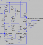
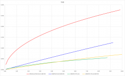
Problem with Ra test simulation
The little simulation is suggesting Ra peaking at 310K and dropping to 5.6K at 20Hz.
Is this something I'm doing wrong or a limitation of the tube model when used in a screen and grid drive configuration?
To display impedance level in ohms, on the waveform window, right click to bring up popup manual, click on the "Manual Limits", on "Left Vertical Axis", select "Linear"
To turn off the phase plot, left click on right axis (phase) to bring up popup manual, click on "Don't Plot Phase".
The little simulation is suggesting Ra peaking at 310K and dropping to 5.6K at 20Hz.
Is this something I'm doing wrong or a limitation of the tube model when used in a screen and grid drive configuration?
Attachments
This means that each cathode winding is 200R and the output voltage will be 24% at the cathode and 76% at the anode when CFb is connected.
Not true, I measured toroidy.pl TTG-CFB4000PP one hour ago, it has 10% CFB related to half primary voltage.
measurement data


- Status
- This old topic is closed. If you want to reopen this topic, contact a moderator using the "Report Post" button.
- Home
- Design & Build
- Software Tools
- LTSpice model for a commercial toroidal output transformer