I have a focusrite scarlett, seems fine to me. There are measurements for it...
The Scarlett is fine but on Windows always verify that the noise floor goes to fs/2 and the LSB is 24bit not 16...
Thank you both for the information.
LIGO "runs" on Python BTW...
import gravity
")
I find it hard to believe that the Python community has missed much ... that is available in Matlab.
Sure, for instance JCX's Python spherical harmonic library looks comparable to the Matlab one I found.
The issue is mostly just convenience, since I already know Fortran.
You mentioned speed in relation to compilers, I noticed that the Python spherical harmonic library has the maths intensive parts done in Fortran.
Makes me feel less old fashioned.
Best wishes
David
Its because he uses a sweep and with a sweep, the number of points is not an issue so why not use more. With a manual setup this is the exact opposite - it is critical to minimize the number of points.
He doesn't really "sweep", just measures at a point then steps to the next one.
So the number of points is surely an issue, he wouldn't spend hours to measure thousands of points if it could be done in a small fraction of the time.
I found the Clio system by Audiomatica has 3-d polar measurement where the full sphere takes 2664 measurement points .
They claim that this is as recommended by the AES standard (AES56-2008).
I don't have a copy of the standard myself so I am unsure if Clio uses brute force to comply or if there is some flexibility.
Anyone AES member have their copy and care to comment?
I think we can do better than that, the question how much, and how.
I am curious that your estimate is so far out of line with Klippel.
Why is your M only 6? I would tend to similar resolution in theta and phi.
That's what the Python spherical harmonics library examples show, for instance
Best wishes
David
Last edited:
I have to admit that I am totally fascinated by the realization that you can make good measurements in such a small, untreated room.
That's the prize that drives all this effort
Thanks for the link, I'll look after work.
Best wishes
David
Just had a quick preview, nice demonstration!
1000 sample points.
Last edited:
I have read some more articles and the klippel stuff more thoroughly.
My understanding so far is that klippel takes the extra points to have "redundant" points to use for the least squares fitting, so to seperate the sound fields of the direct and reflected sound more acurately.
Maybe we could draw/write out an example in 2d with just 1 complex number (one frequency) and one reflection to get a clear picture of the steps that have to be taken?
Found this article, which is quite good I think;
https://jvejournals.com/article/16929
https://jvejournals.com/article/16929
Found this article, which is quite good I think;
https://jvejournals.com/article/16929
So, by that technique, you could construct two planes of mic capsules on an open grid (hardware cloth maybe), and measure with them at different distances from the speaker to remove room reflections? Didn't read in detail yet, only scanned it. But mic capsules can be very cheap (though calibrating them isn't) and a bunch of CMOS analog switches should be able to select through them for sequential measurement?
Anyone is free to choose whatever software they want, I just plan to use REW.
Best wishes
David
Agreed, so any implementation will read in data from any measurements source - including HOLM?
And I should clear up my comment to say that I NEVER saw a sync loss with an internal sound card, only when I went to a USB one. Many people have never seen this problem even WITH a USB sound processor. I feel that you are making too much of this. I have REW, but I don't like it as much as Holm. It's not as convenient.
Last edited:
I noticed that the Python spherical harmonic library has the maths intensive parts done in Fortran.
There is a reason that Intel still supports FORTRAN and that is because it compiles to the fastest code possible short of assembly. They use it in their internal codes for chip development.
My software math is all in FORTRAN specifically for its speed. These are multiple and complex (literally) calculations and the time it takes to do them is not trivial.
Why is your M only 6? I would tend to similar resolution in theta and phi.
That's what the Python spherical harmonics library examples show, for instance
Best wishes
David
My research suggests that there is far less variation in Phi than in Theta. That's why M is lower. I believe that two axi-symmetric sources can have a full 3D sim with just two additional points taken in the vertical direction. Less source symmetry would require more points certainly, but most sources are themselves somewhat symmetric - if not completely.
For example, with my waveguide system, if I add two measurements, one above and one below the axis I can sim the entire 3D field in all directions at all frequencies. It may even be possible with just the simple knowledge of the vertical distance between the two.
Starting out with the intent to do completely general sources is bound to fail because the complexity is far too great. If you don;t start simple, you won't succeed.
Last edited:
Found this article, which is quite good I think;
https://jvejournals.com/article/16929
That is the exact same technique as Wienreich in the planer coordinate system. But we are interested in spherical radiation not near field holography (reproduction back to the source, so that won;t work for us. See Weinreich for the spherical technique that Klippel uses.
[K]lippel takes the extra points to have "redundant" points to use for the least squares fit...
Well spotted! But the redundancy factor is less than 2 I think, not sufficient to explain why Earl's number is so much less.
Maybe we could draw/write out an example in 2d with just 1 complex number (one frequency) and one reflection...
Excellent idea, it's essential to actually work some examples to really understand the maths.
But I'm not ready for it myself just yet, need to learn more first.
Best wishes
David
so any implementation will read in data from any measurements source...?
I doubt it. There is a lack of clarity when we say we want "simple".
An implementation that reads in any measurement source may be simple for a user but it's sure not simple for the implementer.
A simple implementation will be for a specific measurement source, similarly for choice of OS and so on.
I intend to start simple, but try to allow for users to do as they wish.
And I should clear up my comment to say that I NEVER saw a sync loss with an internal sound card, only when I went to a USB one... too much of this.
I realize that this is only a USB card issue but the trend is clearly towards laptops and away from internal cards so I consider it essential that the system work reliably with them.
There is a reason that Intel still supports FORTRAN and that is because it compiles to the fastest code possible short of assembly...
I suspect it's the other way around, it compiles to the fastest code because they support it seriously, to run that vast trove of mathematical code.
Either way, I'm just happy it's still around.
...there is far less variation in Phi than in Theta. That's why M is lower. I believe that two axi-symmetric sources can have a full 3D sim with just two additional points taken in the vertical direction. Less source symmetry would require more points certainly, but most sources are themselves somewhat symmetric - if not completely.
Makes sense, especially for your system with the axi-symmetric horn and bi-lateral symmetric enclosure.
I am personally interested in less symmetric horns, like the old D.B Keele horns that JBL used, or their newer M2.
My cabinets are also less symmetric.
So this tends to require more resolution in phi than your needs.
..bound to fail because the complexity...If you don;t start simple, you won't succeed.
I have previously outlined my proposed simple base and enhancement path for the actual implementation.
But much of my fun is to play with the maths puzzle, try to understand the complexity.
A fully functional 3d scanner that can do anechoic-quality measurements in my own room would be a bonus.
Best wishes
David
Last edited:
...can intrepid DIYers do the same with available software and hardware today?
Aaron, as the software starts to look feasible - have you considered the hardware?
It occurs to me that some of the robotic hardware would be suitable, we basically want a very simple robotic arm.
Main requirement is a simple, compact rotary positioner, presumably a stepper motor and reduction box, probably a planetary unit.
I am sure there are DIY robotics forums to help find this stuff, do you know them?
I have a turret mill with power feed and have looked a little at CNC enhancement, from what I have seen the positioner should be less than the size of a drink can and not too expensive.
Do you know stepper motors?
Best wishes
David
I have read some more articles and the klippel stuff more thoroughly.
My understanding so far is that klippel takes the extra points to have "redundant" points to use for the least squares fitting, so to seperate the sound fields of the direct and reflected sound more acurately.
Maybe we could draw/write out an example in 2d with just 1 complex number (one frequency) and one reflection to get a clear picture of the steps that have to be taken?
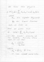
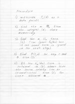
I have attached a short and simplified procedure for 2D. 3D would be almost identical.
Let me know if you have any questions.
PS. I used Lm here for the Legendre Polynomials, but the usual usage is Pm, but this can get confusing with P(r,theta).
OOPS - just under equation 3 the Pm should be Lm.
Attachments
Last edited:
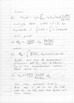
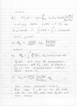
Also, we know that from the hankel function terms there is a cut-in of ka values below which the terms will not contribute (see my book figure 3-6). Basically below the mode number where ka = M there will be almost no contribution to the result. This means that M, the modal number will not be necessary for any frequency below ka.
Now we also know that for M modes we need precisely M data points and more points are just redundant. So the number of required points = maximum modal number. If M=400 then that is like saying we need data for a ka value of 400, which is absurd, ka seldom goes above 20.
The above analysis is slightly simplified since the "cut-in" values for 3D Spherical Harmonics will be different than 2D, but not so much different that 400 data points is necessary to go to 10 kHz.
Hmm, the problematic TI PCM29xx used for your UCA202 is limited to 48 kHz and some of the newer USB sound cards are 96 kHz or more, so presumably use a different codec.
I wonder if they fixed the problem? I am reluctant to use any "it mostly works" solutions.
May as well stay with REW and avoid the sync problem.
There's some USB sound cards that look suitable for this project, with 2-in 2-out to handle loop back, plus built in phantom mike power and pre-amp so less complication from add on boards.
There's a new Behrin*er, or the Focusrite Scarlett looks decent and only ~$50 more.
Any one tried either? Or have a better recommendation?
Best wishes
David
It would certainly be nice if they fixed the problem. "Mostly works" would be a pain for us and any that follow.
I haven't tried a new USB interface yet, but I've got my eye on the UMC22. It's small, inexpensive, and would cut down on set up hassle for me for general acoustic measurements. But for this project, I'd be fine having a dedicated desktop for it.
movie of the pattern the klippel system makes:
UPstage 360|World's First 360deg Smart Speaker in Hi-Res Audio by Level 10 —
Kickstarter
I have to admit that I am totally fascinated by the realization that you can make good measurements in such a small, untreated room. You can hear how typical the room sounds on the video, normally you would not be able to measure anything decent below 300Hz
That video is a great find!
And yes, the idea of getting good full range measurements in a typical room is what started me on this. We may not be able to get there, but it is absolute worth trying to get there, and I'm extremely grateful for all the help so far.
Found this article, which is quite good I think;
https://jvejournals.com/article/16929
I haven't seen that paper before, thank you for sharing.
Maybe we could draw/write out an example in 2d with just 1 complex number (one frequency) and one reflection to get a clear picture of the steps that have to be taken?
I would find that quite helpful to aid understanding how this works.
So, by that technique, you could construct two planes of mic capsules on an open grid (hardware cloth maybe), and measure with them at different distances from the speaker to remove room reflections? Didn't read in detail yet, only scanned it. But mic capsules can be very cheap (though calibrating them isn't) and a bunch of CMOS analog switches should be able to select through them for sequential measurement?
I would think that would be possible, but my assumption is that having near identical frequency and phase response is vital to the system working, hence Klippel using a single microphone and using CNC positioning.
Aaron, as the software starts to look feasible - have you considered the hardware?
It occurs to me that some of the robotic hardware would be suitable, we basically want a very simple robotic arm.
Main requirement is a simple, compact rotary positioner, presumably a stepper motor and reduction box, probably a planetary unit.
I am sure there are DIY robotics forums to help find this stuff, do you know them?
I have a turret mill with power feed and have looked a little at CNC enhancement, from what I have seen the positioner should be less than the size of a drink can and not too expensive.
Do you know stepper motors?
Best wishes
David
I have been thinking about the hardware for awhile, but since the software side is progressing, I'll start giving it more attention. I know there's a pretty good sized online community for DIY CNC, so my plan was to use that as a resource. Although, I'm certainly open for any input for everyone here too. I've been wanting to build a CNC router for some time now, so I have a bit of knowledge, but that project hasn't gotten beyond casual research yet.
Two questions:
Do you think the hardware should have all the movements for a full 3D scan to start with? It seems like staring with super simple is the way to go, but the concept you proposed early on wasn't too much more mechanics for full 3D.
How important is height adjustment for the speaker's platform? Since we want to keep the sound source as far from any boundary as possible, height adjustment would be important, but I'd like some input if it's important enough to include the added complexity.
I have attached a short and simplified procedure for 2D. 3D would be almost identical.
Let me know if you have any questions.
PS. I used Lm here for the Legendre Polynomials, but the usual usage is Pm, but this can get confusing with P(r,theta).
OOPS - just under equation 3 the Pm should be Lm.
Thank you very much for that contribution Earl!
Also, we know that from the hankel function terms there is a cut-in of ka values below which the terms will not contribute... Basically below the mode number where ka = M there will be almost no contribution to the result. This means that M, the modal number will not be necessary for any frequency below ka.
Now we also know that for M modes we need precisely M data points and more points are just redundant. So the number of required points = maximum modal number...
Yes, that's essentially as I understand it for 2-d.
But for an all-purpose measurement system that does not assume symmetries I think we need also similar (even if not identical) resolution in 3-d.
So approximately M squared points, with your example M=20 and so 400 total points, exactly my own ball-park estimate.
The main use of 3-d polars seems to be sound systems for stadiums, auditoriums and the like, where there are speaker arrays and potential interference patterns.
Then ka can be substantially more than your example.
I think this helps explains the AES56 standard, where they use M=72.
But 20 seems a reasonable start for stand-alone speakers and DIY use.
I will study your notes, thanks.
Best wishes
David
It would certainly be nice if they fixed the problem. "Mostly works" would be a pain for us and any that follow.
Shouldn't be a problem with REW and loop back, maybe help anyone who sticks with HolmImpulse.
..my eye on the UMC22. It's small, inexpensive, and would cut down on set up hassle...
Yes, that's the B* box I had in mind, the layout is a bit dumb (the phantom power LED is next to the headphone socket?!) and doesn't have independent output and headphone volume control, not major issues for this use.
Two questions:
Do you think the hardware should have all the movements for a full 3D scan to start with?...
No, we have a consensus to start simple!
But build the simple version with the enhancements in mind
..adjustment for the speaker's platform? Since we want to keep the sound source as far from any boundary as possible...
Same rule, KIS but allow for freedom.
Especially in view of -
1. Rooms don't vary so much in overhead clearance anyway.
2. Inconvenient to have the platform too tall even if there's some improvement in echo-free time.
3. We can mathematically remove most of the echo problem anyway, theoretically at least.
It looks reasonable to make the vertical post a screw in tube, even just for convenient fabrication, and then anyone can make it taller if they measure in a warehouse sized room.
Best wishes
David
Or a nuclear reactor!
Attachments
Last edited:
Yes, that's the B* box I had in mind, the layout is a bit dumb (the phantom power LED is next to the headphone socket?!) and doesn't have independent output and headphone volume control, not major issues for this use.
Typo, it was the UMC202 I had in mind, with 192 kHz 24 bit rather than the 48 kHz of the UMC22.
Not that we really need the 24 bits for polar measurement but that means it can't have the older, suspect chip.
Conceivably the better sample rate could be useful if you want to measure super tweeters or look for compression driver resonances.
And the additional mike pre-amp would simplify microphone comparisons and calibration.
Worth the extra $20 I think.
They added a separate control for monitor volume too, but still the same dumb phantom power LED position.
Best wishes
David
Last edited:
- Home
- Design & Build
- Software Tools
- Klippel Near Field Scanner on a Shoestring