Try grounding the load on the secondary, also why do the transient and AC analysis have different nodes?
The grounding seems to have done the trick - the wave gain behaves more as expected now.
I'm afraid I'm not quite sure what you're asking in the second part of your question; I was comparing input and output wave shapes to see the distortion when I noticed the odd gain changes.
Is there an easier way to find what distortion types are in effect, e.g. harmonic, IM, etc?
I took a look at the FFT output but I don't know how to interpret it.

Using LTSpice to learn is not going well
I have a new issue, and once again I'm not sure if it's down to my misunderstanding of circuits or LTSpice.
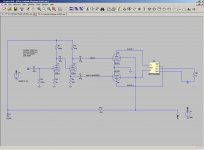
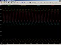
For the circuit below (not complete!) I have displayed what LTSpice is showing me the waveforms are at various points.
I was expecting to see wav-1 and wav-1-inverted to be zero-based and show a wave of approx +/- 12v. I also expected the waves for plate-1 and plate-2 to be the same, but inverted.
Is it me not understanding the circuit, or LTSpice needing some help to find it's feet?
I have a new issue, and once again I'm not sure if it's down to my misunderstanding of circuits or LTSpice.
For the circuit below (not complete!) I have displayed what LTSpice is showing me the waveforms are at various points.
I was expecting to see wav-1 and wav-1-inverted to be zero-based and show a wave of approx +/- 12v. I also expected the waves for plate-1 and plate-2 to be the same, but inverted.
Is it me not understanding the circuit, or LTSpice needing some help to find it's feet?
Attachments
- Status
- This old topic is closed. If you want to reopen this topic, contact a moderator using the "Report Post" button.
- Home
- Design & Build
- Software Tools
- Help with LTSpice... or something else?