I guess the corner is actually a node, but doesn't show as such...
Component terminals, wire ends and wire corners are nodes. Wire corner can be located also in the middle of straight line if you have clicked that point while wiring, or wire is stretched from L-shape to straight by dragging some component in the end. Node is totally invisible if it's not yet junction to other wire.
edit2: the second attachment shows sometimes it does not take.
It takes that. Don't take any screenshots before wire is terminated.
I think I need to take a video. I clicked the wire and it made an anchor but as soon as I move the cursor it starts drawing another wire (this is not the normal behaviour). The second and third screen shot were taken one after the other as part of the same line drawing session ie after I took the screenshot with the wire extending to the right I moved the cursor to the left and then the wire turned green. I could also have gone back to the original termination point and clicked again and it would have created the dot ")
Tony.
Tony.
ok here is a demo that should make it clear what I am talking about
Ignore the turning green when going to the right. I had previously (before I got the screen to gif going) added a line there and then deleted it (so there was a node).
Tony.
Ignore the turning green when going to the right. I had previously (before I got the screen to gif going) added a line there and then deleted it (so there was a node).
Tony.
Attachments
Last edited:
I clicked the wire and it made an anchor but as soon as I move the cursor it starts drawing another wire (this is not the normal behaviour).
You don't terminate the wire after you selected the point at existing wire. Wire will continue if you don't terminate it with Space, Enter or right click, and that is normal and expected because it's designed so.
Wire termination is automatic only at existing nodes, indicated with green highlighted wire.
I think what you are noticing is that it matters which end you start drawing from if you are trying to join the end of a component to the middle of an existing wire.
If you click on the middle of a wire (with no current node) the line will go green when you mouse over the endpoint of a component then with a single click the line will be joined.
However if you start at the component and draw to the middle of a line the line does not go green and the first click only terminates the line segment - as if you were going to draw a right angle, but if you click a second time in the same place it will join the line.
So drawing one way you get a green highlight and only need to click once, drawing the other way you won't get a green highlight and you will have to double click to connect the line.
It is possible to make a change that wire is terminated automatically also when new node and junction is created. That would require green highlight to maintain the same logic.
I'm guessing that next feature request is that new node and junction should be created automatically if user locates a component (terminal) at existing wire. And next after that is library block... This is endless road if we desire more and more.
I'm guessing that next feature request is that new node and junction should be created automatically if user locates a component (terminal) at existing wire. And next after that is library block...
This is endless road if we desire more and more.you will have to double click to connect the line.
Just a short note: double click is not designed feature here. It is: "wire is terminated if you click the same point again". Not much difference in practice but you can have a beer or two between those two clicks.
Last edited:
One option would be forgetting wire nodes and junctions. Many (simple) simulators work without nodes. It's enough that component terminal or endpoint of another wire is lying at the wire. Locating of horizontal components at vertical wires and vice versa is easier, but network parsing would be more complex & slow, and some stretching functions would be different; easier or impossible.
Node system was my favorite but I'm not sure that it is the best compromise.
Node system was my favorite but I'm not sure that it is the best compromise.
Last edited:
Seems to be working well for me now.It is possible to make a change that wire is terminated automatically also when new node and junction is created. That would require green highlight to maintain the same logic.
I'm guessing that next feature request is that new node and junction should be created automatically if user locates a component (terminal) at existing wire. And next after that is library block...
My main concern before was that it was possible to construct circuits that look like wires are connected properly complete with a dot at the junction, but the wires were not really connected, so the circuit would not perform as expected, or at all!
That seems to be fixed now, so I don't care if I have to click once or twice to terminate a connection, as long as what I see when finished connecting lines is an accurate representation of the logical circuit state.
Being able to connect to the middle of lines now without fuss makes modifying and building circuits much easier and more intuitive, as it gives complete freedom when placing components and creating connections.
Last edited:
...it was possible to construct circuits that look like wires are connected properly complete with a dot at the junction, but the wires were not really connected...
It is still possible that you see black dot (fixed part of component terminal) and wire crossing it, but no connection. Missing red dots was the main problem: terminal with wire didn't show red error dot if another end of the wire was open. That programming challenge is now solved. It was not so bad after a break.
While I'm in bug hunt mode I've found that the export schematic option truncates the right hand edge of the text of components if they extend far past the object itself. (I assume a fixed border beside the components closest to the edge is used) Attached is a screenshot of the schematic as well as the exported schematic to show the issue where "Aurum Cantus Left" (and Right) is cut off in the export.
Attachments
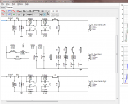
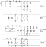
^Yes. That is known feature already discussed on some English forum - maybe here. Width of driver canvas is fixed (for ~13 letters) at the moment, but you can trick the program by adding e.g. short wire on the right. Then crop to smaller with some editor.
Text length detection is very easy to add, but I've skipped that so far.
Text length detection is very easy to add, but I've skipped that so far.
I'm guessing that next feature request is that new node and junction should be created automatically if user locates a component (terminal) at existing wire. And next after that is library block...
hehehe being an LTSpice user I certainly do like how you can place a component in series with an existing wire and it automatically breaks it and inserts the component. Perhaps you could put in some AI that would guess what the user is going to ask for next and pre draw it
Tony.
2.0.3.6 (2018-06-14)
* Segment of existing hor/ver wire is splitted and junction created if user drops terminal of a new component to intermediate point. Applies to adding of capacitor, driver, ground, inductor, op amp and resistor. Not moving.
* Right boundary of schematic export image adapted to length of driver's name.
Wire splitting while adding library blocks would be as easy as single components, but they probably need wiring work anyway.
Small addition to previous.
Setup of the latest 2.0.3.6 build includes also Library\Passive_blocks_V1.zip containing all blocks of version 1. Unzip files to VituixCAD\Library folder if you have old projects to convert from 1 to 2 or find blocks useful otherwise.
New build enables also purging of this kind of "stupid" blocks without attributes via Tune block window.
Last edited:
- Home
- Design & Build
- Software Tools
- VituixCAD