that's great, thanks
a couple more suggestions
- might be nice to have 2 separate lib buttons perhaps, one for passive and one for active
- some search based shortcut feels like it might work well, e.g. type 1st letter of each word in the block name to filter the view (e.g. type LP and you get all the low pass filters, SN gives you a series notch)
so for instance if B were the shortcut for the library block then I could just type BPLP2 and it drops a passive low pass 2nd order in there without needing to use a mouse
thanks, that is useful.
A request on a different subject.... Is it possible to restrict the "mirror missing" option so that it only mirrors on the same axis? I realise the recommendation is to use the same measurement angles on each axis (or rather... now I realise!) but if you don't have this then you have to manually mirror the files or it results in some v strange looking graphs.
EDIT: despite manually mirroring files, I am still seeing some odd results. I have H files that go 0-90 in 10 degree steps and V files that are 7.5 degree steps (so listed as 8,15,23,30,38,45,52,60) to 60 degrees. If I load just the V files, they display normally. If I load just the H files, they display normally. If I load them both and select the horizontal directivity, it looks normal. If I load them both and select vertical, the woofer view goes awol and shows only 0,30,60.
This is with the mirror option turned off btw and having manually mirrored those files.
Last edited:
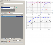
I've got a question regarding the off axis measurements as well. I took measurements to 90 deg at 10, 20, 30, 45, 60, 75, 90
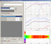
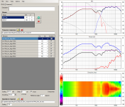
When I put these in I get VERY different spl curve for my crossover, compared to just using the 0deg curves. The differences seem to start to get extreme when I add the 60deg and higher.
Do the measurements have to have a constant variation (ie all 10deg steps, or all 5 deg etc?)
Attached are comparisons of 0deg only and with the zero to 90 deg and with zero to 45 deg.
I'm not sure if there is something wrong with my higher angle measurements or not.
Additionally there seems to be a bug with turning different angles on or off. If I click on the tick box nothing happens. If I double click it, the curve changes, but the tickbox looks the same.
I also tried a sim using my current crossover with the same measurements and compared to actual zero deg measurement with that crossover. When using just the zero deg measurement in the sim, the results were quite close. When using the extra measurements It varies a fair bit (but no where near as extremely as the first three curves below.
I'd like to use the data but at the moment I'm either doing something wrong, or the difference in results is quite scary!!")
edit: added the 4th and 5th graphs, which are the current implementation of the crossover, which I've compared against real measurement.
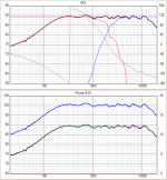
edit2: one additional graph. black actual measurement, green vituix sim with 0deg data. blue vituix sim with 0 through 90 deg data. I'm confused
Tony.
When I put these in I get VERY different spl curve for my crossover, compared to just using the 0deg curves. The differences seem to start to get extreme when I add the 60deg and higher.
Do the measurements have to have a constant variation (ie all 10deg steps, or all 5 deg etc?)
Attached are comparisons of 0deg only and with the zero to 90 deg and with zero to 45 deg.
I'm not sure if there is something wrong with my higher angle measurements or not.
Additionally there seems to be a bug with turning different angles on or off. If I click on the tick box nothing happens. If I double click it, the curve changes, but the tickbox looks the same.
I also tried a sim using my current crossover with the same measurements and compared to actual zero deg measurement with that crossover. When using just the zero deg measurement in the sim, the results were quite close. When using the extra measurements It varies a fair bit (but no where near as extremely as the first three curves below.
I'd like to use the data but at the moment I'm either doing something wrong, or the difference in results is quite scary!!
edit: added the 4th and 5th graphs, which are the current implementation of the crossover, which I've compared against real measurement.
edit2: one additional graph. black actual measurement, green vituix sim with 0deg data. blue vituix sim with 0 through 90 deg data. I'm confused
Tony.
Attachments
Last edited:
This is with the mirror option turned off btw and having manually mirrored those files.
That looks quite funny though fully expected: blended set of partly automatically mirrored data from the other plane, and partly from response files from selected/shown plane.
Basic rules and recommendations:
1) Use integer angles. 7.5, 22.5 deg etc. are rounded to integer.
2) Use the same angle recipe for both hor and ver planes to avoid mixed mirroring. Angles (measured or mirrored) which are common for all drivers are accepted to simulation. 'Enabled' column in response list is not checked if angle is rejected.
3) Constant angle step e.g. 10 degrees is not must but makes life easier due to logical measurement procedure.
4) Measuring of horizontal plane to positive angles only gives quite okay result with circular drivers. Measure both planes if driver is not circular, or to get more accurate result because diffraction effects are not exactly equal to hor/ver. Also negative angles if driver is quite much off the center line.
5) Measure also rear sector 90-180 deg to get more accurate power & DI result. Especially with dipole, bipole and and other omnipolar due to probable asymmetry front to rear. 0-90 deg sector is minimum requirement for unidirectional speakers, but recommended only for wall speakers and very unidirective such as horns.
Few examples:
1) Taipuu 4-way is measured in horizontal plane to both positive (right) and negative (left) angles. Angle step is 10 deg, 36 measurements per driver.
2) Taipuu 3-way is measured in horizontal plane to positive (right) angles only. Angle step is 10 deg, 19 measurements per driver.
Last edited:
Additionally there seems to be a bug with turning different angles on or off. If I click on the tick box nothing happens. If I double click it, the curve changes, but the tickbox looks the same.
Enabled checkbox is read only, just information for user. See previous message.
Double-clicking of response list changes reference angle (axial direction). 'Reference angle' text box tells current axial direction.
Some response simulations looks strange indeed. Verify that:
* All driver instances in the crossover are associated to existing driver in Drivers tab; driver combobox (between schema and parameter list) has correct name.
* Response simulation might also be frozen if crossover network parsing is not successful. Check that all component terminals are connected to other treminals directly or with wire. You can force new parsing e.g. by disconnecting (moving) and reconnecting one ground symbol, or saving + reopening the project.
Just for information that VituixCAD training projects Epe-3W and Kontiainen include also project files for version 2. vxp filename has extension _V2. These projects are for playing with crossover editor and for studying what kind of measurement data is needed and recommended. Projects are measured with Clio which causes angle coding with multiplier x100.
I'm sorry but I don't understand how this is fully expected.That looks quite funny though fully expected: blended set of partly automatically mirrored data from the other plane, and partly from response files from selected/shown plane.
To recap, the graph is taken from a project which has ;
- horizontal: -90 to +90 in 10 degree steps
- vertical: -60, -53, -45, -37, -30, -23, -15, -8, 0, 8, 15, 23, 30, 37, 45, 53, 60
- "Mirror missing angles" option is unchecked
All 3 drivers have the same dataset so 35 measurement files in each way. Every listed file is "enabled" according to the checkbox.
The behaviour seen is:
- horizontal behaves normally, 0-90 degree curves are visible
- vertical behaves abnormally (to my understanding), some measurement angles for the woofer only are simply ignored so the graph appears as those measurements do not exist at all
In fact I just reloaded the project and the visible woofer angles changed from
-60,-30,0,30,60 to -53,-23,23,53 with no change to the data.
Also note that the same measurement files are rendered normally if the H data is not present.
this is a must if you turn on the mirror option isn't it? otherwise the graphs go quite funky as it fills in missing angles from the other dimension. This is why I was asking for the option to only mirror on the same axis.3) Constant angle step e.g. 10 degrees is not must but makes life easier due to logical measurement procedure.
Thanks kimmosto. I probably should have stated that this is an MTM, but the M's have been measured together on the tweeter axis. I've only put in a single driver for the M's in the crossover.
The only change between the graphs above was replacing the driver response curves. first with just the zero deg files and then with the added off axis measurements. I'll do a sim in speakerworkshop, and another in PCD as a sanity check
Tony.
The only change between the graphs above was replacing the driver response curves. first with just the zero deg files and then with the added off axis measurements. I'll do a sim in speakerworkshop, and another in PCD as a sanity check
Tony.
I'm sorry but I don't understand how this is fully expected.
...
- "Mirror missing angles" option is unchecked
Sorry, I didn't notice mirror checkbox status from our previous message. Different angle recipe for hor and ver should work if mirror missing is not checked, but directivity graph might look quite empty due to missing directions.
I would measure same angles in hor and ver to avoid any complications and enable full mirroring. Usually I have circular cones and domes -> measuring verticals is not must.
Mirroring checkbox might be quite easy to split in two: "same plane" and "opposite plane", but usually users won't encounter problems because they don't measure verticals or use the same recipe than with horizontal. I will check possibilities for split...
In fact I just reloaded the project and the visible woofer angles changed from
-60,-30,0,30,60 to -53,-23,23,53 with no change to the data.
Some curves could stay in memory after some invisible conflict due to performance optimization. I'll try to fix these when noted.
this is a must if you turn on the mirror option isn't it?
Variable step is not a problem. For example angle step to rear sector 100...180 deg could be double. Just repeating that you shouldn't have problems is all drivers and both planes are measured with the same angle recipe. This has been okay for years in ver 1, and ver 2 looks the same to me.
Last edited:
I've only put in a single driver for the M's in the crossover.
Perhaps it was missing impedance scaling? You should scale Z response of single driver with 0.5 that crossover would see impedance of original two drivers in parallel.
Just repeating that you shouldn't have problems is all drivers and both planes are measured with the same angle recipe.
Unfortunately I have to continue this to avoid extra work.
You can measure circular woofer in horizontal plane only to positive angles 0-90/180 with steps of 10. Same recipe for circular dome. Check Mirror missing.
But, if you have hor/ver asymmetrical planar tweeter in the same project, you must measure both horizontal and vertical planes. Horizontal and vertical angle recipe of planar tweeter must be equal to avoid wrong mirroring (from hor to ver or vice versa). No need to measure 0 and 180 deg vertically because they are already included in horizontal set (program skips these automatically too).
What I'm also saying, splitting 'Mirror missing' into two separate checkboxes wont help much. By unchecking "Mirror missing hor to ver" checkbox we would loose possibility to measure less directions with symmetrical radiators. Vertical plane is needed to calculate power & DI effects of multiple radiators with different Y (or Z) coordinates.
No the impedance is actual measurement in cabinet with both drivers connected.
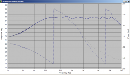
I ran the same sim in speakerworkshop and it matches almost exactly the 0deg only simulation from vituixcad. Black is the speaker workshop sim, blue is the exported vituixcad sim.
I'll check my off axis measurements, perhaps there is something screwy with the phase in some of them.
Tony.
I ran the same sim in speakerworkshop and it matches almost exactly the 0deg only simulation from vituixcad. Black is the speaker workshop sim, blue is the exported vituixcad sim.
I'll check my off axis measurements, perhaps there is something screwy with the phase in some of them.
Tony.
Attachments
Last edited:
OK fair enough, I will remember to use the same angles in futureBut, if you have hor/ver asymmetrical planar tweeter in the same project, you must measure both horizontal and vertical planes. Horizontal and vertical angle recipe of planar tweeter must be equal to avoid wrong mirroring (from hor to ver or vice versa). No need to measure 0 and 180 deg vertically because they are already included in horizontal set (program skips these automatically too).
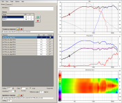
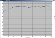
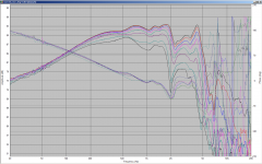
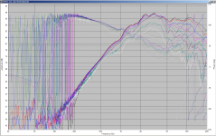
OK I've put all of the measurements on the same graph. Nothing really sticks out for me. One thing I did wonder about was the lowest frequencies being at a lower level at the more extreme angles. I wasn't sure whether they should all be starting from a similar origin there is 1.6db difference between the 90 deg measurement and on axis at 20 Hz (although gating was set at around 300Hz, so maybe that has an effect).
Tony.
Tony.
Attachments
Wintermute, for the off axis angles, how did you measure them?
If you measured off axis angles by rotating the speaker, and keeping the mic at the same position, you most likely are not measuring the angle you think you are measuring.
This is a very subtle mistake that I've never seen mentioned anywhere, but it makes a fairly big difference. If you are simply rotating the speaker, you are most likely rotating at the wrong point of rotation. If you rotate the speaker like how a turntable would rotate the speaker, then the point of rotation is at the center of the speaker. This is wrong, because the center of rotation needs to be at the driver you're measuring. You can easily see why this is wrong. Place the speaker on axis, and have the mic point directly at one of the drivers, say the tweeter. Then rotate the speaker 45 degrees. Notice the mic is no longer directly pointing at the tweeter. In fact, it is probably not even pointing at the front baffle! The angle between the mic and the tweeter is not 45 degrees, but an angle greater than 45 degrees.
I thought that we already discussed about rotation, but let me link this once again: VituixCAD Measurement Preparations.pdf
There you can find recommendation for valid measurement gear, programs, settings, rotation method, center points etc. Exception is that typical small M and T can be measured at the same (average) elevation if they are close to avoid mic movement between measurement sequences. Angle error in vertical plane is typically 3-4 degrees at 1m which is okay. Few main things imo:
* Timing of all measurements are normalized to known physical origin i.e. center point of driver on baffle surface or distance differences from mic to driver's origin are known, that measurement data can be located (with X,Y,Z mm parameters) to virtual 3D space in simulation. Semi-dual channel measurement mode or constant latency gear without IR peak normalization is must.
* Off-axis angles are close the same for different drivers. Absolute accuracy is not relevant here because power & DI is always "just" approximation when based on dual plane measurements. Manual rotation table with angle scale is fully adequate.
Last edited:
Optimizer questions
First of all I have to say that I am excited with Vituixcad and with Kimmo!
1. What i need to do in order to change the target line from 85dB? I see the video that i have to drag the ends of line but it does not work with my mouse!...?
I can adjust the target per way, but I cannot change the axial and power targets.
2. Can I use instead of power response as a second target, only one measurement for optimization, e.g. 45 degrees? How to use this instead of power?
3. Also interesting should be instead of power response to optimize the early reflections as described by Toole. Can we choose only these measurements instead of sound power?
4.Similarly to the early reflections target, instead of Power response, could we use Listening window ( average of +/- 15 and 3- degrees as described by Toole) instead of one measurement for reference axis?
Thanks a lot for your help
Vassilists,
1. Press and hold Shift key while dragging ends of target line. I suppose this is in user manual but not sure.
2. Select Axial and Power response optimisation, adjust Weight factor of Axial response to 100% (and Power to 0%), change Reference angle to 45 deg, adjust target line in SPL graph and start Optimizer.
3. Optimizing reflections only is not possible.
4. Yes, but vertical sector could be zero or equal to horizontal sector.
Load limited frequency response set -15...+15 deg to one driver to cheat power calculation. After that Enabled column is checked 0...15 deg with all drivers. Select Intensity on cylinder surface in Options window. This changes intensity calculation to average pressure and includes 0 deg response. Select Axial and Power optimisation, adjust Weight factor of Power response to 100% (and Axial to 0%), adjust target line in Power graph and start Optimizer. Verticals are ignored by unchecking Include vertical in Options window.
- Home
- Design & Build
- Software Tools
- VituixCAD