Level tuning possibilities with fully passive crossover are very limited - within less than 1 dB.
Struggling to understand what you are trying to say here ? Limited in what way ?
Last edited:
Limited in what way ?
After you have adjusted tonal balance close to perfect with passive crossover, you probably don't want to change level of tweeter (with L-pad) more than about 0.5 dB up or down. There is no absolute limit of course, but sound won't be so perfect anymore.
After you have adjusted tonal balance close to perfect with passive crossover, you probably don't want to change level of tweeter (with L-pad) more than about 0.5 dB up or down. There is no absolute limit of course, but sound won't be so perfect anymore.
I agree, although I don't see the connection to the original post by gfiandy.
") I assume he already has the tweeters padded to the correct level for frequency response but now wants to easily calculate the power dissipation of the tweeter taking into account that attenuation.
I assume he already has the tweeters padded to the correct level for frequency response but now wants to easily calculate the power dissipation of the tweeter taking into account that attenuation.Not that he is adding attenuation to the tweeters without consideration for frequency response.
I have a similar situation on my speakers where the tweeters have about 5dB of attenuation in the final design - which means the dissipation of the tweeters is also quite low for a given input power. But that was of course done to match sensitivity with the baffle step corrected midbass driver.
0.5dB is actually a large error for the attenuator of a tweeter since it is affecting several octaves, (large area under the curve) so it will definitely sound wrong with the tweeter 0.5dB too high or too low.
Relative attenuation levels of different drivers in a multiway system I find critical to a fraction of a dB (say 0.2dB) because each driver is covering several octaves, whereas a response error over a fraction of an octave 1dB or more may not be audible at all.
I agree, although I don't see the connection to the original post by gfiandy.
I just asked some questions from gfiandy, and that was additional comment because I didn't see reason to calculate tweeter's power dissipation if one cannot do much about it with L-pad in pure passive system.
Anyway, I will consider adding driver power, amplifier output power and some indication about maximum SPL produced with given voltage/power.
Hi, my reason was pretty much what Simon is saying.
It is quite common in small speakers for the tweeter level to be reduced by arround 3dB even up to 10dB. If the tweeter is say a 20w part and the woofer a 100W part. It would be good to know that with the crossover attenuation the tweeter is OK to rate the system at 100W.
Often this is done with a L pad but sometimes a simple series resistor with a capacitor or RC in parrallel with the tweeter can work better as it gives you another degree of freedom in adjusting the response.
Thanks,
Andrew
Output and drivers added to power dissipation graph. Checkboxes to reduce amount of visible curves.
Few other small changes too. See changelog. Export file format for IFFT is added for configuration tool of FourAudio. It's quite generic, but probably not very valuable.
An externally hosted image should be here but it was not working when we last tested it.
Few other small changes too. See changelog. Export file format for IFFT is added for configuration tool of FourAudio. It's quite generic, but probably not very valuable.
You're welcome. I also found output and driver power curves interesting. They are not mandatory, but give additional information how much and where power is lost. That information may reduce bad decisions when optimizing frequency response or noise floor too aggressively or foolishly.
I agree. The power dissipation display is excellent.Excellent, thank you for this. I just had a quick look at it and it looks like it will be a really helpful extra piece of information on system performance.
Its amazing how fast you can pull these changes together.
Thank you.
Andrew
As I've completed my crossover work for now (except for a little value tweaking over long term listening) I am only opening the program from time to time but it seems that every time I do there is an update and new features!
Someone may wonder how total output volt-ampere (VA) and total output real power (W) are calculated with fully active or multi-amplified or hybrid multi-way with two or more power amplifiers where phase angle of impedance/current doesn’t effect to other ways because ways are “isolated” by amplifiers.
Output power of passive system with common power amplifier is simply P=U^2/Z. Volt-ampere (VA) is magnitude, and real power (W) is real part of the magnitude. This will work also for individual active ways, but not for total output.
Way is handled as an active with dedicated power amplifier if there is at least one enabled active block. Output volt-ampere (VA) of this group is sum of volt-amperes of all active ways, and output real power (W) is sum of real powers.
Total output power of multi-amplified passive system can be simulated by adding useless active block (e.g. PEQ with gain=0 dB) to ways having dedicated amplifier.
If system has both active ways with dedicated amplifiers and passive ways with common amplifier, total output VA is sum of volt-amperes of passive and active groups, and total output W is sum of real powers of passive and active groups.
All this mess only for combining total output power into two curves with some logical manner.
Thanks for Kimmosto's great simulator.I have an additional suggestion for your software update.In the ENCLOSURE menu,the type of vent is circle by default.Vent of triangle or rectangle is possible to be added in the simulation process.It will be far better I reckon because sometimes I build some pro audio loudspeakers when I'm working on this simulation program.Thanks for adopting such a constructive idea.
Best Regards
Best Regards
Oh,thanks.How about vent velocity added?^Area [cm2] option has already been added today in rev 1.1.31.0. That is easier with other shapes than circle.
Kimmosto
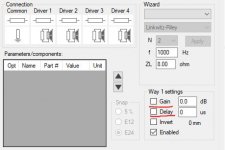
This may have been asked and answered but here it is: the "gain" and "delay" should, IMO, switch the respective functions (with some data entered) on and off when the boxes are checked/unchecked. However they seem to be on always? The two functions below them (invert and enabled) however do react to the box checking.
Thanks.
Attachments
First off, VituixCAD is simply a brilliant piece of software. My hats off to you.
Any chance the 15 filter block limit can be either removed or increased? I'm doing DSP work and trying to get really accurate response curves, and I would need more than 15. Really accurate driver correction alone needs more than 15. Then I need filters to optimize for the off axis response.
Thanks
P.S. Is there a way to donate? VituixCAD is really awesome!
Last edited:
- Home
- Design & Build
- Software Tools
- VituixCAD