Hi there,
I'm a pretty new to this forum.
I'm trying to learn designing techniques to for Hi-Fi whci is very interesting and also much harder than I believed.
I also bought a good book called "small circuit design audio" written from D. Self which it has a lot of useful information and seems to be an excellent book.
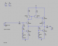
As exercise I'm designing a low distortion) buffer, and I'm using LTSpice to have an idea about the THD from the circuit.
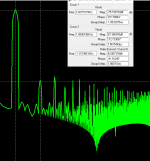
According to LTSpice I have a second order harmonic distortion of -87.7 dbV (relative to first haromic so is dBV_fs )
How much do you trust LTSpice results in term of HD?
Do you use a different simulator?
Thank you.
I'm a pretty new to this forum.
I'm trying to learn designing techniques to for Hi-Fi whci is very interesting and also much harder than I believed.
I also bought a good book called "small circuit design audio" written from D. Self which it has a lot of useful information and seems to be an excellent book.
As exercise I'm designing a low distortion) buffer, and I'm using LTSpice to have an idea about the THD from the circuit.
According to LTSpice I have a second order harmonic distortion of -87.7 dbV (relative to first haromic so is dBV_fs )
How much do you trust LTSpice results in term of HD?
Do you use a different simulator?
Thank you.
Attachments
This simulator can be trusted at such levels of distortion.
You check this circuit. Pay attention to R1. This resistor symbolizes the output resistance of the volume control. Many amplifiers make a large distortion when receiving a signal from a source with high output resistance. This amplifier does not introduce such distortions due to T2. You can verify this if you remove the jumper for about R1: THD of about 0.000,16% or 0.000,18% for 20 kHz .
You check this circuit. Pay attention to R1. This resistor symbolizes the output resistance of the volume control. Many amplifiers make a large distortion when receiving a signal from a source with high output resistance. This amplifier does not introduce such distortions due to T2. You can verify this if you remove the jumper for about R1: THD of about 0.000,16% or 0.000,18% for 20 kHz .
Attachments
Hi.
Yes, I designed this amplifier.
I'll be glad if you will build the amplifier on the basis of this circuit.
If you add a few transistors, you'll get the results even better.
For both amplifiers compulsory installation of capacitors C3 shown or greater capacity. It is necessary for sustainability.
Yes, I designed this amplifier.
I'll be glad if you will build the amplifier on the basis of this circuit.
If you add a few transistors, you'll get the results even better.
For both amplifiers compulsory installation of capacitors C3 shown or greater capacity. It is necessary for sustainability.
Attachments
Thank you T117!
I will build one prototype during the Xmas break and let you know.
I made further simulation with your ciurcuit and the NF is about 4.9 nV/sqrHz with the 1/f noise of 2 nv/sqrhz! better than any OA I can think of (considering the high impedance from the source). I have tried to increase theinput impedance with some bootstrapping, but as result I have higher HD and higher NF! So not good... the circuit seems good as is.
I could use this preamp to amplify even a guitar considering its 220kohm input stage!
Regarding C4 and C6 do you think if I use electrolytic capacitor it will introduce some HD?
( apology for the question I'm very new to the world of High Fi, and from what I can see you are an expert).
How much do you trust LTSpice results in term of HD?
Do you use a different simulator?
Thank you.
It's the models not the simulator, IEEE floating point math is -300dB
numerically.
I checked: the condition of the zero output resistance of the signal source is HD = 0.000,041%, with 40 kom HD = 0.000,3%. It's bad, but it's not a tragedy. You can compare these data with other HD opamp or amplifiers in the same conditions. There will be worse.I made further simulation with your ciurcuit and the NF is about 4.9 nV/sqrHz with the 1/f noise of 2 nv/sqrhz! better than any OA I can think of (considering the high impedance from the source). I have tried to increase theinput impedance with some bootstrapping, but as result I have higher HD and higher NF! So not good... the circuit seems good as is.
C4 can be electrolytic with a capacity of 100 or 330 UF, but the S6 is a better film good quality (for audiophiles).
- Status
- This old topic is closed. If you want to reopen this topic, contact a moderator using the "Report Post" button.
- Home
- Design & Build
- Software Tools
- Simulating THD with LTSpice