In Sprint-Layout program for example, when I draw the board outline to show the shape of the PCB, does that line make the board smaller
or is that border line included in the board? Stupid question maybe but in my project the PCB must be exactly of certain size...
Not at all. The CENTER of the line is the actual edge of the pcb. Usually you want a thin line at the edge, 0.01" - 0.02."
Thank you. So the thickness of that line tells me how much my rectangular board is losing length and width when manufactured...
More precisely, the center of the line IS the edge of the board, independent of how thick the line is.
This line won't appear on the board though, unless you place it on the top silk screen layer.
Last edited:
Thank you. So the thickness of that line tells me how much my rectangular board is losing length and width when manufactured...
No! That is NOT what he said!
Consider a line of zero width. That is what marks the board outline (or any other feature or dimension).
Now, do you want to see the line on the screen or on a printout? Yes, of course, so you need to give it a real finite thickness. That is all.
Hmm...
If the center of the line is the real edge of the board then half of the line will be lost on all edges when the board is manufactured. So one whole line is lost vertically and horizontally...in my case it is 0.5mm. I find it acceptable.
The board outline definition is normally on a special layer which is not visible. Although not normally done, you can add a visible outline on the top silkscreen layer.
In this case, you can move it inward slightly so that the entire width of the lines is within the actual board outline. Make sure that the board house understands this.
The board outline definition is normally on a special layer which is not visible. Although not normally done, you can add a visible outline on the top silkscreen layer.
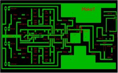
That is true. In Sprint-Layout program the pcb-outline color is white. See attachment.
Attachments
In my experience, the most common practice is to place the outline in a separate file by itself. The center of the line will be the edge of the completed PWB. (At least that's what I've experienced among the handful of fabricators I've used over the last 10 years or so. I seem to recall seeing fabricators who asked for an outline defined by a line of a particular width, placed on a particular layer. And at least once I noticed a fabricator who said the board would be machined to the INSIDE edge of the outline line.)In Sprint-Layout program for example, when I draw the board outline to show the shape of the PCB, does that line make the board smaller or is that border line included in the board? Stupid question maybe but in my project the PCB must be exactly of certain size...
As the old camel-trader said, "Only Allah is perfect.". Every physical manufacturing operation is subject to a tolerance. You may have to read the fine-print in your manufacturer's "Terms and Conditions", or "Standard Specifications", documents to discover how much variation from "perfect" is acceptable to your supplier. The seat of my pants says that for prototype PWB's the outline dimensions, and mounting hole locations, typically vary up to a few thousandths of an inch (roughly 0.05 mm) or so. If you truly require tighter tolerances you will probably have to pay for special handling.
(In fact, just last week I put the calipers on a pair of prototypes. There WAS a difference, which I knew beforehand because one of the boards fit onto a test fixture much more easily than the other. I don't recall what the variation was but it was within the "few thousandths" that I expected. I made a slight modification to the fixture.)
Dale
If you truly require tighter tolerances you will probably have to pay for special handling.
No, that's not the issue. If the width of the board is in the range 159.5...160.0mm, that's fine by me...
I set the board outline thickness at 150 mils to let me know how far away to keep components from the edge. Later I change it to 10 mils for fab. This is on the drill gerber.
Four of our suppliers use the centre of the line for board edge.
The other supplier uses extreme outside edge of copper for board edge because all they have is top and bottom copper and the drill ( .tap) file to work with. (two day fast board)
Internal routing for board panelization is another story for another day.
")
Four of our suppliers use the centre of the line for board edge.
The other supplier uses extreme outside edge of copper for board edge because all they have is top and bottom copper and the drill ( .tap) file to work with. (two day fast board)
Internal routing for board panelization is another story for another day.
The copper layers should not go to the exact edge of the board, they should be slightly pulled back so the cutting is not into the copper.I set the board outline thickness at 150 mils to let me know how far away to keep components from the edge. Later I change it to 10 mils for fab. This is on the drill gerber. Four of our suppliers use the centre of the line for board edge. The other supplier uses extreme outside edge of copper for board edge because all they have is top and bottom copper and the drill ( .tap) file to work with.
Some programs do this automatically.
The copper layers should not go to the exact edge of the board, they should be slightly pulled back so the cutting is not into the copper.
Some programs do this automatically.
Are you referring to:
" The other supplier uses extreme outside edge of copper for board edge because all they have is top and bottom copper and the drill ( .tap) file to work with."
How does the board mfg know where the edge of the board is if there is only top and bottom copper?
They cut to the edge of the copper...see .jpg
Otherwise the board ends up smaller than you want it and will not fit the slots where it needs to be mounted. ( I speak from experience
)Attachments

For reference . . . . the Seeed studio "Fusion PCB Specification" page at http://support.seeedstudio.com/knowledgebase/articles/447362-fusion-pcb-specification is a very complete reference to the tolerances and capabilities of a typical PWB fab house. The many graphical illustrations are especially helpful to understanding what the terms mean!
In my mind, just having that web page could convince me to give my business to Seeed Studio rather than one of a dozen competitors.
Dale
In my mind, just having that web page could convince me to give my business to Seeed Studio rather than one of a dozen competitors.
Dale
For any PWB layout program that can legitimately be called a PWB layout program, you can set up the real-time DRC to flag violations of the board-edge keepout area.The copper layers should not go to the exact edge of the board, they should be slightly pulled back so the cutting is not into the copper.
Some programs do this automatically.
(Depending on the vendor, the board-edge keepout requirement ranges from 10 mils (0.010"; 0.25 mm) to 25 mils (0.65 mm). There's a good illustration on the Seeed Studio specification page at Fusion PCB Specification ? Feedback & Ideas for seeed . Their board-edge keepout is 15 mils.)
Last edited:
That sounds like a good idea! COMPONENT setback from the board edge is typically a requirement related to automated insertion and soldering equipment. The copper keepout area around the board edge is imposed by the PWB fabrication process.I set the board outline thickness at 150 mils to let me know how far away to keep components from the edge. Later I change it to 10 mils for fab. This is on the drill gerber . . . .
Dale
Could someone help me to identify the problem with drillings on my layout? When I create drill file in Sprint, it says 239 drillings on the silkscreen layer and they will be ignored. As a result, exported drill file have all drillings in one corner of PCB.
Also, how to save in Gerber files cut out area in ground plane? In Sprint the layout is fine with applied cutouts, in gerber all cutouts disappeared.
Thanks.
Also, how to save in Gerber files cut out area in ground plane? In Sprint the layout is fine with applied cutouts, in gerber all cutouts disappeared.
Thanks.
- Status
- This old topic is closed. If you want to reopen this topic, contact a moderator using the "Report Post" button.
- Home
- Design & Build
- Software Tools
- PCB layout design problem.