Read the Electronics World "Hotter Spice" available in "IansArticles" on myDrive...
Re XTI in the VDMOS (tempco for the Is parameter). Thanks. I never noticed that...
Thanks for the comments and the article, that provides history to explain some of the minor anomalies that mystified me.
For instance, it never occurred to me that your work-around of XTI could have such a simple explanation, I assumed some deep technical issue
 .
. Best wishes
David
I see you have moved from New Zealand to Aus, where are you?
Hi everyone. In the current LTSpice library, all MOSFET models have been augmented with the parameter "ksubthres=0.1". I don't know when this occurred, but it makes sense and should increase the accuracy of these models simply because a small ksubthres parameter is probably always better than no subthreshold modeling at all.
Aside from that, the addition of this parameter has positive effects on overall simulator performance, because it eliminates the discontinuity in the original model that was caused by the missing subthreshold region.
If you haven't recently, take a look through the changelog.txt in the LTSpiceXVII program folder. Lots of interesting stuff there. I wonder if ADI is providing help with development?
Last edited:
Might make mention of this model before it disappears from the internet, although perhaps for academic interest now as the device is heading to a better place.
5LN01** which was an old Sanyo part had a surprisingly detailed model, for something that a manufacturer would publish. Not only includes subthreshold conduction but also channel length modulation/punchthrough and fairly representative capacitance.
Disappointingly none of the higher voltage relations ever had anything that detailed (like the p-channel 5LP01 and the currently still active 1HP04/1HN04). I do wonder what the motivation for such a detailed model was.
5LN01SS: Small Signal MOSFET 50V 0.1A 7.8 Ohm Single N-Channel SSFP
Does anyone have a LTSpice model for Infineon BSP129? I don't know how to get the factory model to import. I tried using a generic N channel MOSFET symbol and changed specifier to "X" and used name of model but got error that number of nodes do not match...
Thanks in advance.
Power' 'MOSFET' 'Simulation' 'Models - Infineon Technologies
Thanks in advance.
.SUBCKT BSP129 drain gate source Tj Tcase PARAMS: dVth=0 dRdson=0 dgfs=0 dC=0 Zthtype=0
.PARAM Rs=0.027 Rg=10 Ls=3n Ld=1n Lg=3n
.PARAM Inn=0.025 Unn=0 Rmax=20
.PARAM act=0.54
X1 d1 g s Tj K_240_d_var PARAMS: a={act} dVth={dVth} dR={dRdson} Inn={Inn} Unn={Unn}
+Rmax={Rmax} dgfs={dgfs} Rs={Rs} dC={dC} heat=1
Rg g1 g {Rg}
Lg gate g1 {Lg*if(dgfs==99,0,1)}
Gs s1 s VALUE={V(s1,s)/(Rs*(1+(limit(V(Tj),-200,999)-25)*4m))}
Rsa s1 s 1Meg
Ls source s1 {Ls*if(dgfs==99,0,1)}
Ld drain d1 {Ld*if(dgfs==99,0,1)}
Rth1 Tj t1 {166.55m+limit(Zthtype,0,1)*61.64m}
Rth2 t1 t2 {730.55m+limit(Zthtype,0,1)*270.37m}
Rth3 t2 t3 {7.81+limit(Zthtype,0,1)*741.69m}
Rth4 t3 t4 {7.4+limit(Zthtype,0,1)*9.35m}
Rth5 t4 Tcase {7.8+limit(Zthtype,0,1)*9.85m}
Cth1 Tj 0 13.4u
Cth2 t1 0 7.5u
Cth3 t2 0 149.668u
Cth4 t3 0 1.95m
Cth5 t4 0 48.845m
.ENDS
Power' 'MOSFET' 'Simulation' 'Models - Infineon Technologies
Last edited:
X1 inside the subcircuit refers to K_240_d_var which is another subcircuit defined in some other library. Can you find this model?
The model doesn't contain references to or parameters for a standard model such as NMOS or VDMOS, so unless we can find and use K_240_d_var, we would have to make a model from scratch or just use SiMetrix.
The model doesn't contain references to or parameters for a standard model such as NMOS or VDMOS, so unless we can find and use K_240_d_var, we would have to make a model from scratch or just use SiMetrix.
I found the subcircuit. It looks like an explicit implementation of the MOSFET model, which kind of model I'm not sure. However if you .inc both this and your model in the LTSpice schematic that gets us closer.
Code:
.SUBCKT K_240_d_var dd g s Tj PARAMS: a=1 dVth=0 dR=0 dgfs=0 Inn=1 Unn=1 Rmax=1
+gmin=1 Rs=1 Rp=1 dC=0 heat=1

.PARAM  Vth0=-1.05     beta4c=0.243   ph0=20         ph1=0.026      Ubr=290
.PARAM  Rd=1.95        nmu=2.6        Rf=0.2         rpa=0.06877    lnIsj=-24.7
.PARAM  Rdi=0.2

.PARAM  Tref=298     T0=273      auth=3m      c=0.82       mu_bet=0.4
.PARAM  f_bet=-2     ndi=1.2     UTnbr=207m   lnBr=-23     kbq=85.8u
.PARAM  Wcml={beta4c*4*c}
.PARAM  aubr={0.93m*UBr}
.PARAM  dvgs={0.1-0.06*Vth0}

.PARAM  f1=65p         f2=69p         f3=139p        f4=360p        f5=270p
.PARAM  U0=0.5         nd=0.47        nc=0.5         g1=1.9         bb=-7
.PARAM  sl=45p         remp=0p        ta=60n         td=20n

.PARAM  Vmin=-1.75      Vmax=-0.65        dCmax=0.35
.PARAM  Vth={Vth0+(Vmax-Vth0)*limit(dVth,0,1)-(Vmin-Vth0)*limit(dVth,-1,0)}
.PARAM  p0={Wcml*a*((1-f_bet)*(T0/Tref)**mu_bet+f_bet)    }
.PARAM  Rlim={(Rmax-Rs-(Unn-Vth0-Inn*Rs-SQRT((Unn-Vth0-Inn*Rs)**2-4*c*Inn/p0))/(2*c*Inn))/(1+rpa*(Inn/a)**2)}
.PARAM  dRd={Rd/a+if(dVth==0,limit(dR,0,1)*max(Rlim-Rd/a,0),0)}
.PARAM  bet={Wcml}

.PARAM  dC1={1+dCmax*limit(dC,0,1)}
.PARAM  Cox={f1*a*dC1}
.PARAM  Cds0={f2*a*dC1}
.PARAM  Cgs0={f3*a*dC1}
.PARAM  Cox1={f5*a*dC1}
.PARAM  Crand={remp*SQRT(a)}
.PARAM  dRdi={Rdi/a}

.FUNC U1(Uds,T)       {(SQRT(1+4*(0.4+(T-T0-25)*2m)*abs(Uds))-1)/2/(0.4+(T-T0-25)*2m)}
.FUNC I2(p,Uee,z1,pp) {if(Uee>pp,(Uee-c*z1)*z1,p*(pp-p)/c*exp((Uee-pp-(min(0,Uee))**2)/p))}
.FUNC Ig(Uds,T,p,Uee) {bet*((1-f_bet)*(T0/T)**mu_bet+f_bet)*I2(p,Uee,min(Uds,Uee/(2*c)),min(2*p,p+c*Uds))}
.FUNC Iges(Uds,Ugs,T)
 +{a*(sgn(Uds)*Ig(U1(Uds,T),T,1/(ph0-ph1*T),Ugs-Vth+auth*(T-Tref))+exp(min(lnBr+(abs(Uds)-UBr-aubr*(T-Tref))/UTnbr,25)))}

.FUNC Isjt(Tj)           {exp(min(lnIsj+(Tj/Tref-1)*1.12/(ndi*kbq*Tj),9))*(Tj/Tref)**1.5}
.FUNC Idiode(Usd,Tj,Iss) {exp(min(log(Iss)+Usd/(ndi*kbq*Tj),9))-Iss}
.FUNC Idiod(Usd,Tj)      {a*Idiode(Usd,Tj,Isjt(Tj))}

.FUNC QCdg(x,z)  {if(f4>f5,(f5**2-(f4-z*sl)**2)/(2*sl)+f5*min(x,(f4-f5)/sl),f4*z-sl*z**2/2-f5*max((f4-f5)/sl-x,0))}

E_Edg     d   ox  VALUE {V(d,g)-(min(V(d,g),-bb)+1/(g1*(1-nc))*((1/(1+g1*max(V(d,g)+bb,0)))**(nc-1)-1))}
C_Cdg     ox  g   {Cox}
E_Edg1    d   ox1 VALUE {V(d,g)-QCdg(V(d,g),limit(V(d,g),(f4-f5)/sl,f4/sl))/f5}
C_Cdg1    ox1 g   {Cox1}
C_Cdg2    d   g   {Crand}

E_Eds     d edep  VALUE {(V(d2,s)-I(V_sense3)/Cds0)}
C_Cds  edep    s  {Cds0}
C_Cds2   d2    s  {Cds0/500}

C_Cgs     g    s  {Cgs0}

G_chan    d    s  VALUE={Iges(V(d,s),V(g,s),T0+limit(V(Tj),-200,350))}
E_RMos   d1    d  VALUE={I(V_sense)*(Rf*dRd+(1-Rf)*dRd*((limit(V(Tj),-200,999)+T0)/Tref)**nmu)*(1+rpa*(I(V_sense)/a)**2)}
V_sense  dd   d1  0
G_diode   s   d2  VALUE={Idiod(V(s,d2),T0+limit(V(Tj),-200,499))}
R_Rdio   d2   d3  {dRdi}
V_sense2 d1   d3  0

L_L001    a    c  {td/(ta+td)}
R_R001    a    b  {1/ta}
V_sense3  c    f  0
R_sense3  f    0  1
E_E001    b    0  VALUE {I(V_sense2)}
E_E002    e    0  VALUE {1Meg*Cds0*(1/(1-nd)*U0**nd*(limit(U0+V(d2,s),U0/2,2*UBr))**(1-nd)+2**nd*min(V(d2,s)+U0/2,0))}
R_R002    e    c  1Meg

R1        g    s  1G
Rd01      d    s  500Meg
Rd02     d2    s  500Meg
Rd03     d1    d  10k

G_TH      0    Tj  VALUE = {heat*LIMIT(I(V_sense)*V(dd,s),0,100k)}

.ENDSHi Keantoken,
The complete model library can be downloaded here as a zip file. It has instructions in pdf files along with symbols etc. I just don't know enough to make use of it.
Thanks,
X
Here is the K_240_d_var Sbckt that is inside the .lib file:
Edit: we just posted at same time...
p.s., there are not a lot of depletion mode MOSFETs (I think you can count them on one hand) so surprising no one has used this recently in DIYA as an LTSPice model. I just used the BSP129 as a CCS in the VAS of a circuit (actual protype) and it works very well with a simple pot to regulate and set current. Being a SOT223, it is nicely packaged for a compact implementation.
The complete model library can be downloaded here as a zip file. It has instructions in pdf files along with symbols etc. I just don't know enough to make use of it.
Thanks,
X
Here is the K_240_d_var Sbckt that is inside the .lib file:
**************************************************************************************
.SUBCKT K_240_d_var dd g s Tj PARAMS: a=1 dVth=0 dR=0 dgfs=0 Inn=1 Unn=1 Rmax=1
+gmin=1 Rs=1 Rp=1 dC=0 heat=1
.PARAM Vth0=-1.05 beta4c=0.243 ph0=20 ph1=0.026 Ubr=290
.PARAM Rd=1.95 nmu=2.6 Rf=0.2 rpa=0.06877 lnIsj=-24.7
.PARAM Rdi=0.2
.PARAM Tref=298 T0=273 auth=3m c=0.82 mu_bet=0.4
.PARAM f_bet=-2 ndi=1.2 UTnbr=207m lnBr=-23 kbq=85.8u
.PARAM Wcml={beta4c*4*c}
.PARAM aubr={0.93m*UBr}
.PARAM dvgs={0.1-0.06*Vth0}
.PARAM f1=65p f2=69p f3=139p f4=360p f5=270p
.PARAM U0=0.5 nd=0.47 nc=0.5 g1=1.9 bb=-7
.PARAM sl=45p remp=0p ta=60n td=20n
.PARAM Vmin=-1.75 Vmax=-0.65 dCmax=0.35
.PARAM Vth={Vth0+(Vmax-Vth0)*limit(dVth,0,1)-(Vmin-Vth0)*limit(dVth,-1,0)}
.PARAM p0={Wcml*a*((1-f_bet)*(T0/Tref)**mu_bet+f_bet) }
.PARAM Rlim={(Rmax-Rs-(Unn-Vth0-Inn*Rs-SQRT((Unn-Vth0-Inn*Rs)**2-4*c*Inn/p0))/(2*c*Inn))/(1+rpa*(Inn/a)**2)}
.PARAM dRd={Rd/a+if(dVth==0,limit(dR,0,1)*max(Rlim-Rd/a,0),0)}
.PARAM bet={Wcml}
.PARAM dC1={1+dCmax*limit(dC,0,1)}
.PARAM Cox={f1*a*dC1}
.PARAM Cds0={f2*a*dC1}
.PARAM Cgs0={f3*a*dC1}
.PARAM Cox1={f5*a*dC1}
.PARAM Crand={remp*SQRT(a)}
.PARAM dRdi={Rdi/a}
.FUNC U1(Uds,T) {(SQRT(1+4*(0.4+(T-T0-25)*2m)*abs(Uds))-1)/2/(0.4+(T-T0-25)*2m)}
.FUNC I2(p,Uee,z1,pp) {if(Uee>pp,(Uee-c*z1)*z1,p*(pp-p)/c*exp((Uee-pp-(min(0,Uee))**2)/p))}
.FUNC Ig(Uds,T,p,Uee) {bet*((1-f_bet)*(T0/T)**mu_bet+f_bet)*I2(p,Uee,min(Uds,Uee/(2*c)),min(2*p,p+c*Uds))}
.FUNC Iges(Uds,Ugs,T)
+{a*(sgn(Uds)*Ig(U1(Uds,T),T,1/(ph0-ph1*T),Ugs-Vth+auth*(T-Tref))+exp(min(lnBr+(abs(Uds)-UBr-aubr*(T-Tref))/UTnbr,25)))}
.FUNC Isjt(Tj) {exp(min(lnIsj+(Tj/Tref-1)*1.12/(ndi*kbq*Tj),9))*(Tj/Tref)**1.5}
.FUNC Idiode(Usd,Tj,Iss) {exp(min(log(Iss)+Usd/(ndi*kbq*Tj),9))-Iss}
.FUNC Idiod(Usd,Tj) {a*Idiode(Usd,Tj,Isjt(Tj))}
.FUNC QCdg(x,z) {if(f4>f5,(f5**2-(f4-z*sl)**2)/(2*sl)+f5*min(x,(f4-f5)/sl),f4*z-sl*z**2/2-f5*max((f4-f5)/sl-x,0))}
E_Edg d ox VALUE {V(d,g)-(min(V(d,g),-bb)+1/(g1*(1-nc))*((1/(1+g1*max(V(d,g)+bb,0)))**(nc-1)-1))}
C_Cdg ox g {Cox}
E_Edg1 d ox1 VALUE {V(d,g)-QCdg(V(d,g),limit(V(d,g),(f4-f5)/sl,f4/sl))/f5}
C_Cdg1 ox1 g {Cox1}
C_Cdg2 d g {Crand}
E_Eds d edep VALUE {(V(d2,s)-I(V_sense3)/Cds0)}
C_Cds edep s {Cds0}
C_Cds2 d2 s {Cds0/500}
C_Cgs g s {Cgs0}
G_chan d s VALUE={Iges(V(d,s),V(g,s),T0+limit(V(Tj),-200,350))}
E_RMos d1 d VALUE={I(V_sense)*(Rf*dRd+(1-Rf)*dRd*((limit(V(Tj),-200,999)+T0)/Tref)**nmu)*(1+rpa*(I(V_sense)/a)**2)}
V_sense dd d1 0
G_diode s d2 VALUE={Idiod(V(s,d2),T0+limit(V(Tj),-200,499))}
R_Rdio d2 d3 {dRdi}
V_sense2 d1 d3 0
L_L001 a c {td/(ta+td)}
R_R001 a b {1/ta}
V_sense3 c f 0
R_sense3 f 0 1
E_E001 b 0 VALUE {I(V_sense2)}
E_E002 e 0 VALUE {1Meg*Cds0*(1/(1-nd)*U0**nd*(limit(U0+V(d2,s),U0/2,2*UBr))**(1-nd)+2**nd*min(V(d2,s)+U0/2,0))}
R_R002 e c 1Meg
R1 g s 1G
Rd01 d s 500Meg
Rd02 d2 s 500Meg
Rd03 d1 d 10k
G_TH 0 Tj VALUE = {heat*LIMIT(I(V_sense)*V(dd,s),0,100k)}
.ENDS
*$
**************************************************************************************
Edit: we just posted at same time...
p.s., there are not a lot of depletion mode MOSFETs (I think you can count them on one hand) so surprising no one has used this recently in DIYA as an LTSPice model. I just used the BSP129 as a CCS in the VAS of a circuit (actual protype) and it works very well with a simple pot to regulate and set current. Being a SOT223, it is nicely packaged for a compact implementation.
Last edited:
This model has 5 pins because it is an electrothermal model - it will model dynamic thermal effects!
So you will need to add 2 more pins to the MOSFET symbol in order to use it. The Tj pin should be floating, the Tc pin can be connected to ground for now which will simulate an infinite heatsink.
So you will need to add 2 more pins to the MOSFET symbol in order to use it. The Tj pin should be floating, the Tc pin can be connected to ground for now which will simulate an infinite heatsink.
This model has 5 pins because it is an electrothermal model - it will model dynamic thermal effects!
So you will need to add 2 more pins to the MOSFET symbol in order to use it. The Tj pin should be floating, the Tc pin can be connected to ground for now which will simulate an infinite heatsink.
Wow, a full blown elctrothermal model - can see heat generation and thermal runaway etc. cool, err I mean hot...
I do not know how to add 2 more pins to the MOSFET symbol and how to set to ground etc? More hand-holding needed here...
I've attached a demo file along with a symbol that will work with it. See if it work right for you.
Thanks Keantoken!
Hey, I just saw your Kuartlotron buffer - cool! Topology brought to mind the DLH amp/buffer I just played with. 4 actives and super low distortion. In case you haven't seen it. I will definitely try your K buffer though. I love 4 to 5 transistor circuits.
DLH Amplifier: The trilogy with PLH and JLH amps
Edit:
regarding your example schematic for the BSP129, what do I do with the txt file?
So I tried opening the .asc file and get an error missing symbol. How do I link the symbol txt file?
-Thanks.
Last edited:
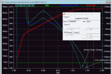
LTspice Infineon subcircuit BSP129 plots
Thanks Keantoken, excellent work as usual
I'd like to know what type of MOSFET model Infineon use. Anyone recognise it?
Attached are some Vgs and Vds plots to check out the model. They plot two curves each. Stepped Tj non-electrothermal. OR you can plot a Fixed Tj plus an electrothermal. You choose which ones by changing the .Step commands: turn one off and the other on then re-Run. Some findings:
- The Vds plot you can see subthreshold conduction is modelled and the threshold temp co is modelled.
- The Vds-2V plots show entering saturation where there are abrupt changes in the slope just like LTspice vdmos. There is no drain conductance in saturation -- not sure if it is set to zero, or if it is not modelled. It's not obvious from the listings on how to set the drain conductance like Lambda does in the VDMOS. Anyone know how?
- The Vds-50V sweep shows the drain conductance in saturation increases as Tj rises -- this is something that standard (isothermal) models do not give and at lower audio frequencies could easily change simulated distotion in many designs.
Attachments
Last edited:
Thanks Keantoken, excellent work as usual
I'd like to know what type of MOSFET model Infineon use. Anyone recognise it?
Attached are some Vgs and Vds plots to check out the model. They plot two curves each. Stepped Tj non-electrothermal. OR you can plot a Fixed Tj plus an electrothermal. You choose which ones by changing the .Step commands: turn one off and the other on then re-Run. Some findings:
These seem to be excellent models. Obviously a lot of work has gone into developing them and making them available for a fairly wide range of simulators. The Introduction PDF Table 2.1 says the PSpice code ".lib" does SiMetrix, LT-Spice, and Multisim. Early documents are dated 2006.
- The Vds plot you can see subthreshold conduction is modelled and the threshold temp co is modelled.
- The Vds-2V plots show entering saturation where there are abrupt changes in the slope just like LTspice vdmos. There is no drain conductance in saturation -- not sure if it is set to zero, or if it is not modelled. It's not obvious from the listings on how to set the drain conductance like Lambda does in the VDMOS. Anyone know how?
- The Vds-50V sweep shows the drain conductance in saturation increases as Tj rises -- this is something that standard (isothermal) models do not give and at lower audio frequencies could easily change simulated distotion in many designs.
The transition into the subthreshold region of conduction looks a little too sharp. Comments?
Cheers,
Bob
Hi Keantoken, just wanted to say Thank you again. Here is where the BSP129 model ended up at:
AKSA's Lender Preamp with 40Vpp Output
You should like it, a 4 BJT (not including the BSP129 as a CCS) preamp with gain and 40vpp muscle.
AKSA's Lender Preamp with 40Vpp Output
You should like it, a 4 BJT (not including the BSP129 as a CCS) preamp with gain and 40vpp muscle.
IXYS IXTH80N20L and IXTH48P20P models by David Zan
Attached 2 models for the IXYS linear MOSFETs IXTH80N20L and IXTH48P20P created by David Zan.
Permission for distribution here: Fully Differential Amplifier With CMCL
The simulation of a class AB amplifier using these models was very successful verified in a real amplifier here 2stageEF high performance class AB power amp / 200W8R / 400W4R.
Code:
* David Zan, (c) 2017/03/02 Preliminary
.MODEL IXTH80N20L VDMOS Nchan Vds=200
+ VTO=4 KP=15
+ Lambda=2m
+ Mtriode=0.4
+ Ksubthres=150m
+ Rs=5m Rd=10m Rds=200e6
+ Cgdmax=9000p Cgdmin=300p A=0.25
+ Cgs=5500p Cjo=11000p
+ Is=10e-6 Rb=8m
+ BV=200 IBV=250e-6
+ NBV=4
+ TT=250e-9

* David Zan, (c) 2017/03/02 Preliminary
.MODEL IXTH48P20P VDMOS Pchan Vds=200
+ VTO=-4 KP=10
+ Lambda=5m
+ Mtriode=0.3
+ Ksubthres=120m
+ Rs=10m Rd=20m Rds=200e6
+ Cgdmax=6000p Cgdmin=100p A=0.25
+ Cgs=5000p Cjo=9000p
+ Is=2e-6 Rb=20m
+ BV=200 IBV=250e-6
+ NBV=4
+ TT=260e-9
Attachments
Last edited:
- Home
- Design & Build
- Software Tools
- Better power MOSFET models in LTSpice