Thanks Hans. I'm using a delay of 10 cycles followed by 10 measurement cycles just for working out what input voltages I need to get the output powers I'm interested in (0.1W, 0.5W, 1W. 2W etc).
Then I'm using a delay of 900 cycles followed by 100 measurement cycles with 2**12 data points for the actual THD measurements and FFT.
It's set up like this (copied from elsewhere in this thread):
.options
+ plotwinsize=0
+ noopiter
+ numdgt=7
+ method=gear
+ numdgt=15
+ ptrantau=0
.param
+ F= 1000
+ FFT=2**12
+ dlycyc=900
+ numcyc=100
+ ;<-change
+ dlytime=dlycyc/F ;needs somewhere
+ simtime=numcyc/F+dlytime
+ timestep=(simtime-dlytime)/FFT
.tran 0
+ {simtime}
+ {dlytime}
+ {timestep} ;For High Precision FFT
I'll play around with your suggestions.
Problems with sync release in LTXVII
I installed LTXVII about a month ago, and after I solved the initial issues, all eventually seemed to run smoothly....
Until today: it asked for an update, and I agreed.
Unfortunately, the update has broken everything: now when I attempt to open an existing schematic, it is unable to find any symbol, including the native ones.
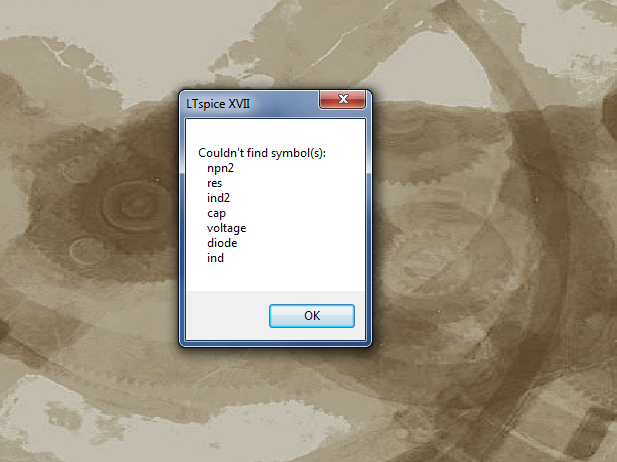
When I start from a blank sheet and I add symbols, I see them in the list, but when I pick them, nothing appears.
Any ideas about the cause of these troubles?
When I installed LTXVII, I didn't opt for the default location, because my C is almost full, but until the sync release, it didn't seem to pose problems
I installed LTXVII about a month ago, and after I solved the initial issues, all eventually seemed to run smoothly....
Until today: it asked for an update, and I agreed.
Unfortunately, the update has broken everything: now when I attempt to open an existing schematic, it is unable to find any symbol, including the native ones.
When I start from a blank sheet and I add symbols, I see them in the list, but when I pick them, nothing appears.
Any ideas about the cause of these troubles?
When I installed LTXVII, I didn't opt for the default location, because my C is almost full, but until the sync release, it didn't seem to pose problems
Attachments


Help
LTSpice IV
Using Cree SiC FET library for 3 years with no problem, now AC Analysis error:
"Unsupported mixture of time dependent and arbitrary behavior in .AC analysis"
Other .AC analysis simulations, which do not contains this library, are working.
Wrong control panel value?
LTSpice IV
Using Cree SiC FET library for 3 years with no problem, now AC Analysis error:
"Unsupported mixture of time dependent and arbitrary behavior in .AC analysis"
Other .AC analysis simulations, which do not contains this library, are working.
Wrong control panel value?
Attachments
I have a model IR2010 but that did not work, I have a 2110 this do work but the singals looks so bad, special the driver output.
Someone have better ones, or corrected version I have now 10 x IR2010S who I go use for the amp, but that did not work, model in zip.
regards
Someone have better ones, or corrected version I have now 10 x IR2010S who I go use for the amp, but that did not work, model in zip.
regards
Attachments
Last edited:
Has anyone used Eagle to import a .asc file into Eagle? I just got a new updated version of Eagle 9.1.1 and it is showing an import of an .asc file directly into Eagle.
Thanks for any information.
I have the new version but see not a import of a .asc file, but I have the free version.
I do not use eagle much anymore, I do not like internet connection and put design at risc. I use a old dos ultiboard, the best there is for mine work.
Why do output stage changes impact earlier stage when there is no feedback
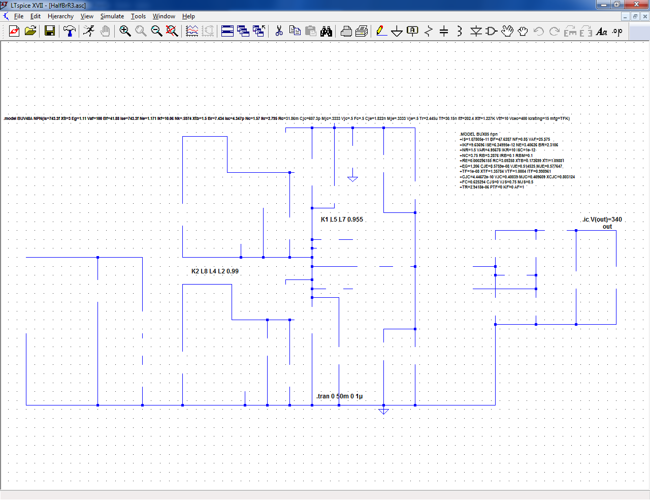
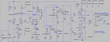
Hi. I have an amp simulation in which changes to the output stage are causing distortion in the input stage when there is no feedback.
A screen shot of one of many variants of this simulation is attached. I've noticed the problem on lots of occasions but here is an example.
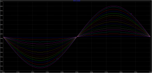
The first screenshot shows the first anode voltage as the input is stepped from 0.02V peak through 0.75V, steps of 0.05V. You can see spikes on the 4 highest voltage curves.
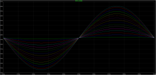
If I increase the output stage quiescent current from 18mA to 289.5mA (unrealistic but it serves to illustrate the problem) the distortion spikes disappear (3rd screenshot).
Any suggestions please?
Hi. I have an amp simulation in which changes to the output stage are causing distortion in the input stage when there is no feedback.
A screen shot of one of many variants of this simulation is attached. I've noticed the problem on lots of occasions but here is an example.
The first screenshot shows the first anode voltage as the input is stepped from 0.02V peak through 0.75V, steps of 0.05V. You can see spikes on the 4 highest voltage curves.
If I increase the output stage quiescent current from 18mA to 289.5mA (unrealistic but it serves to illustrate the problem) the distortion spikes disappear (3rd screenshot).
Any suggestions please?
Attachments
Last edited:
Thanks Ray. The bottom rail is all at -150V.Try grounding the bottom (common) rail.
Could the observed effect be due to differing loading as the presets are varied in value ? i.e. nothing to do with the output stage as such.
If you remove U1 and U2 do you still see the same effect.
I'm wondering if something non linear (clamping effect) is happening with the FET that alters as you alter the gate bias.
If you remove U1 and U2 do you still see the same effect.
I'm wondering if something non linear (clamping effect) is happening with the FET that alters as you alter the gate bias.
I would like to see the schematic with models if possible since this can be hard to narrow down definitively.
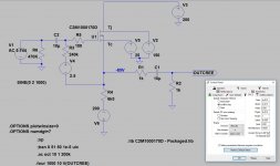
Thanks keantoken. Model attached. Everything you need should be in the zip file.
This morning I copied all the files into a separate folder. Before zipping I opened the model file and ran it to make sure all was OK. Would you believe that I couldn't reproduce the problem?
I closed LTSpice (I've often wondered about problems like this being a result of something like a memory leak) and re-opened the original model. Same.
So, I modified the transformer and the problem returned. Closed and reopened LTSpice just to be sure, and it was still there.
Attachments
Q1 and Q9 are turning off during operation, creating spikes. This spike is worse than would occur realistically because the OnSemi models use NMOS which doesn't include subthreshold conduction and so their transconductance shoots to zero when they turn off.
Increase the bias on these transistors and/or use VDMOS models that include the ksubthres= parameter (which will be more accurate). The builtin VDMOS models in LTspice should all have this (although they may just use a generic value of ksubthres that doesn't reflect reality).
Increase the bias on these transistors and/or use VDMOS models that include the ksubthres= parameter (which will be more accurate). The builtin VDMOS models in LTspice should all have this (although they may just use a generic value of ksubthres that doesn't reflect reality).
Thanks keantoken. I did some research and came across the Better power MOSFET models in LTSpice thread. Lots of treatment of this issue there.
Doubling the bias eliminated the problem.
I assume I have to know the identity of a suitable VDMOS device in order to pick it from the builtin VDMOS models. Can you please suggest something equivalent to the N-Channel Power MOSFET 600V, 2.0Ω that I'm using?
Alternatively, can I just include the ksubthres=parameter in my existing FDPF5N60NZ model? Of course, then there's the question of what I should set it too. I'm not seeing anything obvious in the datasheet.
What is the mechanism in the simulation by which the turn-off behaviour of the 2 MOSFETs impacts the first stage of the amp?
In fact, they do.probably because the output tube models don't do grid and screen current well.
- Home
- Design & Build
- Software Tools
- Installing and using LTspice IV (now including LTXVII), From beginner to advanced