This is what I got.
Your quite a way behind the latest version then.
Your system and set up is an unknown and we don't know what settings and so on have carried over from build to build or even from a W7 to W10 upgrade.
Without having the PC in front of you it is hard to diagnose for sure but I don't think at this point it is anything related to W10 itself.
Something is odd with your setup.
Try a clean install from an ISO file you create yourself. Type 'Media Creation Tool' into the search box to get the latest MS build of W10 and just do a clean default install. Then install LT.
Mark... lets see if we are done and dusted with a clean install. If its still a problem then we can look at thread splitting.
What have I missed?
I need a subcircuit for a particular comparator that is not included with LTspice.
It is the ADCMP600, an A.Devices product so a bit poor it's not included now AD owns LTSpice.
But "no problem" I think to myself, I'll just copy an LT comparator and modify it.
So the symbols are in the LTspiceXVII\Lib\Sym\Comparators folder, as expected.
I choose the LT1711 because the symbol matches.
But no LT1711 entry in LTspiceXVII\Lib\Sub folder...
What have I missed, where is it?
Anyone have an ADCMP600 model handy or comments on comparator models?
I know how flaky many of the opamp models are, any recommendations for a decent comparator base model?
David
Dave I have successfully used the LT1720 voltage comparator macromodel, which is presupplied in LTSPICE.
Here is the enclosing circuit where that chip was deployed: [link to diyAudio thread]
Maybe my requirements for a simulation model are more stringent, or less stringent, than yours. Have a look and decide for yourself.
Here is the enclosing circuit where that chip was deployed: [link to diyAudio thread]
Maybe my requirements for a simulation model are more stringent, or less stringent, than yours. Have a look and decide for yourself.
OK, I'm back in business.
Fresh installed Windows 10 in both laptop and desktop, updating it and checking LTSpice XVII running fine with each update. If something went wrong I could go back and delete the problematic one. Everything went fine, so now I can run things again.
Hans, if you can now let me know what the problem was in running OPA134, that could only run in XVII.
Dave I have successfully used the LT1720 ...
Thanks Mark, I didn't explain myself very well, the comparator was a cue for a problem I want to clarify rather than the problem itself.
That is, that I can find the ASY symbol of a particular component but not the SUB that actually implement the behaviour.
I suspect it's buried in a LIB file and probably encrypted because I can't even find an occurrence of the name LT1711 (or LT1720 or whatever) in the folder.
So I would like to confirm how LTspice links the two components, in other words how the SUB folder and file system works.
As to the comparator specifically, like you I ended up at the 1720 and it works.
I would still like to see the implementation, I expect it's OK and Mike E. didn't allow the sort of junk code used by some models, but I would like to study it.
Can you find the LT1720 subcircuit?
Best wishes
David
that is work you will have to do yourself
OK, done.
The symbol links to the SUB via an attribute in the ASY file rather than the name of the ASY file.
Similarly the name of the sub circuit is in the SUB file rather than the name of the SUB file.
If the SUB is encrypted then you are screwed.
I don't know when LTspice loads all the information in the files, it can't just check file names and resolve references as needed.
If I add a new ASY symbol then I can't see it in LTspice until there is some sort of buffer flush and it reloads the information.
Anyone know how to force this nicely?
Turn the computer off and on every time is a PITA.
Sync release seems to work.
David
Last edited:
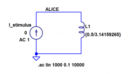
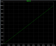
Hans, I am going to assume you intend to use SPICE's ".AC analysis". If so then the little subcircuit below gives you a voltage which is proportional to frequency.
Not only that, the linear function ( y = mx + b ) has the super convenient property that b=0 and m=1. In other words, one volt per Hertz ... with no dc offset (!)
Now you can use this voltage in a behavioral source to get the two terminal transfer function you want, including the AC analysis frequency. See post #2348 in this thread for inspiration.
(and if you intend to use SPICE's ".TRANsient analysis" instead, you'll probably need to build a little tachometer circuit (charge pump) whose output voltage is proportional to frequency). A google image search for tachometer circuit ought to get you started.
Mark Johnson
_
Attachments
I would like to create a frequency dependant floating resistor, like
R= A*(B+C*sqrt(freq))
this can not be done with .Param R=etc.
Any help would be welcome.
Hans
Hello Hans
Frequency dependent resistor is quite a new idea for me.
Would you explain what you mean?
What component behaves like that?... a coil ?
Why do you need to sim it ?
I would really like to know more.
Best
Ricardo
Hi Hans,I would like to create a frequency dependant floating resistor, like R= A*(B+C*sqrt(freq))
this can not be done with .Param R=etc.
Any help would be welcome.
Hans
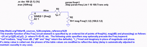
Maybe this can do it? B sources (complete reference) - LTwiki-Wiki for LTspice
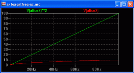
R=1 mag Freq(1,1,0) (100,0.1,0) implements the BR function, here with mag=1 at 1Hz then mag=10 at 100Hz with phase of 0 throughout. It needs a start frequency and end frequency. You choose these to suit the frequency range in your analysis.
This shows the R is 10 at 10Hz and 100 at 100Hz. Phase is zero.
The .trans run for my example doesn't look good; it's unstable long term. Not sure why. Does it need more more than 2 points? Maybe you or someone can get the .Trans mode to work OK. This is the first time I have tried this. All the best.
Attachments

Hi Hans,Hi Ricardo,
When simulating a transmission line, the series resistance R increases proportional with the frequency as from a certain point and 1/G goes with goes with the sqrt.
Hans
Have you seen Cyril Bateman's cable simulation article? He modeled a Tx line (speaker cables) with eg Rseries=11m+72u*Sqrt(f) using 200 RLC elements. Also his 1/G was modeled with frequency. An example showing driving impedance plot can be viewed here Simulation: Cyril Bateman's Amplifier-Speaker cable interactions
Blue is simulated and Red is measured (with a real speaker at the other end). His article can be downloaded here 404 Not Found
IIRC Cyril used MC7 because it allowed R to be made frequency dependent. I think LTspice can be used for this also, as I suggested, but obviously using a different syntax.
BTW Cable #55 was made by Cyril using Raychem (type 55) insulation with two layers IIRC of braid stripped from coax. This cable blew up both of his Blameless amps! It was the reason he did this research on cables. Unfortunately his research was never completed due to failing health (and death RIP).
I just wonder where Alice came from, she must be someone
She came from Professor Ron Rivest of MIT. When discussing (secure) communication protocols, Alice and Bob are the two entities who communicate. Those names have proven to be easier to think about, than the cold, lifeless "A" and "B".
Wikipedia article about Alice and Bob and Ron Rivest
- Home
- Design & Build
- Software Tools
- Installing and using LTspice IV (now including LTXVII), From beginner to advanced