You'll get used to it ")
I had a look at both the documents lib folder and the one in program files shortly after Scott posted tbh. Opened them with notepad but couldn't find the default NJF model. I've been looking on and off ever since
I also don't know why LTXVII has the two lib folders.
I had a look at both the documents lib folder and the one in program files shortly after Scott posted tbh. Opened them with notepad but couldn't find the default NJF model. I've been looking on and off ever since
I also don't know why LTXVII has the two lib folders.
Scott... I'm only running LTXVII these days but enlighten me
I just made those up as an example and included them in the sim, I don't think modifying the built in primitive model is allowed or would even make sense it would be lots of complicated code. My install says LTXVII but I have not upgraded it in two years, unless by accident. The behavior is such that all the PFET models will be behave in the wrong way.
Last edited:
Thanks Scott. That explains why I couldn't find 'em and I understand your question much better now.
OK, so that's probably one to put to Mike Engelhardt. He's very approachable on things like this and is directly contactable via the 'Help' and 'About' tabs within the program.
Any reason for not syncing to the latest release ? There is a changelog .txt file in the program files but nothing mentioning FET's that I can see.
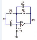
You can use a current input source to simulate an I/V convertor but not with that basic configuration.
i do not understand what you mean by "basic configuration"
Just the way you have the opamp configured. Its an inverting amp at DC and low frequency. At higher frequency the 1nF starts to allow the non inverting input to alter the whole phase relationship of input vs output.
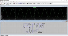
An I/V convertor would use a current source and that would feed directly into the non inverting input.
This shows an I/V convertor (first opamp) and the output from that opamp.
An I/V convertor would use a current source and that would feed directly into the non inverting input.
This shows an I/V convertor (first opamp) and the output from that opamp.
Attachments
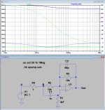
To find the input impedance, just place a small resistor in series with a voltage source.
Zin will be R4*(Va)/(V(a)-V(b)).
In this case the impedance starting with 80dB or 10K at 1 Khz and ending at 73.44dB or 4K7 at 1 Mhz.
Output impedance is depending on the OPA used and can be found in the manufacturers specs.
Hans
Zin will be R4*(Va)/(V(a)-V(b)).
In this case the impedance starting with 80dB or 10K at 1 Khz and ending at 73.44dB or 4K7 at 1 Mhz.
Output impedance is depending on the OPA used and can be found in the manufacturers specs.
Hans
Attachments
Last edited:
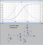
Try it this way: replace the voltage source with a current source (flipped so the arrow points up) set to 1A AC , do an AC analysis and measure the voltage at the current source, then right click on the DB scale at the left of the graph and change it to logarithmic, you now get a reading directly in ohms.
Last edited:
the methods in posts 1096/7 give the same results for input impedance, however the results alter with the opamp used i.e. LT1028 13k2 at 100hz and 3k9 at 100k, whereas for a "universal opamp" I get 20k at 100hz and 3k9 at 100k.
I thought the circuitry used would define the output impedance....Output impedance is depending on the OPA used and can be found in the manufacturers specs.
- Home
- Design & Build
- Software Tools
- Installing and using LTspice IV (now including LTXVII), From beginner to advanced