You don't right click the text "RightClickMe", you right click the symbol on the schematic as stated in my post, the same way as you would the symbol for a transistor for example.
"To use the symbol "triode-w1_dd.asy", select component (F2), navigate to the "misc" folder, select "triode-w1_dd", place the symbol on the schematic. Right click on the symbol and a dialog will appear. Right click or double left click on the "SpiceModel" line (RightClickMe) and a drop-down box will appear. Left click your chosen model. Hit enter."
I'm using LTspice IV.
Is anybody have LT3045 model for LTSpice IV?
...no, I will never install XVII, until it stay such a .... :-(
I had kontakt with the writer, and he go look at the code, it opens two .raw windows and crash, it is slower then the old version.
However the writer has no interest in us so he takes the time.
regards
Sorry to be a pain. But when I try to save the file in the sub folder I get a message that I do not have permission to save the file in the .sub folder. How do I get around this? My computer does not have a separate user and administrator log in, they are the same. And when I have Spice running run under "run as administrator" it doesn't help.
This is probably because you have LTspice installed in \Program Files (x86)\LTC\LTspiceIV\... and everything within and under the \Program Files (x86)\ folder is protected by Windows. I didn't run into this problem on my own installation (Windows 8.1 upgraded to Windows 10), but I've seen other people have this problem. Try looking here:
Can't Write to Program Files folder
Writing To Program Files Folder - How (Access Denied) ? Solved - Windows 7 Help Forums
If you google "write to program files windows 8" or similar, you should find lots of forum posts from people with this problem. Many have answers that may help you. Good luck with it.
--
Thanks rongon, I looked at your links and copied spice to a new folder named "My Program Files." It made it possible to save the text file to the sub folder. But the 6N13S model does not come up in the drop down in "right click me." I'm assuming it's because that model wasn't in the file at the time it was attached to the symbol.
I've added and removed models from the triode-w1_dd.txt file many, many times without any problems. I don't know what you are doing wrong..? One caveat though... if you remove a model and it just so happens to be the same model that you are using in the schematic, you will have to delete the symbol and place it again for the drop-down to appear. Adding a new model will show up immediately in the drop-down.Thanks rongon, I looked at your links and copied spice to a new folder named "My Program Files." It made it possible to save the text file to the sub folder. But the 6N13S model does not come up in the drop down in "right click me." I'm assuming it's because that model wasn't in the file at the time it was attached to the symbol.
I've added 4 new models to the file for your convenience. Just un-zip and replace. Make sure it's in the \lib\sub folder as that is where the symbol file will look for it.
1) 6AS7
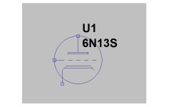
2) 6N13S (a new Curve Captor model I traced today)
3) 6N13S_AN (new Ayumi model I traced today)
4) 6N13S_EK (Eugene V. Karpov Koren model)
Attachments
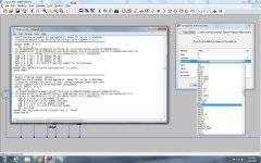
Make sure the file "triode-w1_dd.txt" is located at "C:\Users\User\Documents\LTspiceXVII\lib\sub\triode-w1_dd.txt" and there's not a duplicate file at C:\Program Files\LtspiceXVII\lib\sub if 64bit or Program Files (x86)\LtspiceXVII\lib\sub if 32bit version. It looks like the symbol file is reading an older version of the sub file that doesn't have the 6N13S model added.This is getting really frustrating. I've attached a screen capture that shows my problem. I used the file in the above post. Once again 6N13S shows up in the sub file but not in the drop down.
I don't use that broken version of LTspice nor Windoze. I'm running LTspiceIV in wine on Linux Mint 17.3 KDE. I have used the drop-down in Windows Seven and it worked perfectly. I did take ownership of the LTspiceIV install directory though.
")
Is LTspiceXVII somehow caching that file?

Let's try this. Edit the triode-w1_dd.asy file to tell it exactly where to look for the model file:
In other words, put the full path to where the triode-w1_dd.txt file is located in the line:
SYMATTR ModelFile
Code:
Version 4
SymbolType CELL
LINE Normal -48 0 -28 0
LINE Normal -20 0 -12 0
LINE Normal -4 0 4 0
LINE Normal 12 0 20 0
LINE Normal 28 0 36 0
LINE Normal 0 -48 0 -16
LINE Normal -20 -16 20 -16
LINE Normal -20 -12 20 -12
LINE Normal -20 -16 -20 -12
LINE Normal 20 -16 20 -12
LINE Normal -24 12 24 12
LINE Normal -32 48 -32 20
LINE Normal -24 12 -32 20
LINE Normal 24 12 32 20
LINE Normal -28 16 28 16
CIRCLE Normal -48 -48 48 48
WINDOW 0 8 -64 Left 2
WINDOW 38 8 -34 Left 2
SYMATTR Prefix X
SYMATTR Description This symbol is for use with a subcircuit macromodel that you supply.
SYMATTR ModelFile C:\Users\User\Documents\LTspiceXVII\lib\sub\triode-w1_dd.txt
SYMATTR SpiceModel RightClickMe
PIN 0 -48 NONE 0
PINATTR PinName Plate
PINATTR SpiceOrder 1
PIN -48 0 NONE 0
PINATTR PinName Grid
PINATTR SpiceOrder 2
PIN -32 48 NONE 0
PINATTR PinName Cathode
PINATTR SpiceOrder 3SYMATTR ModelFile
Last edited:
555 Timer Delay vs multiple input pulse
Hi all
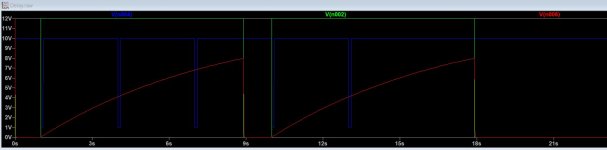
I am stuck in generating a delay circuit with an input with multiple pulses.
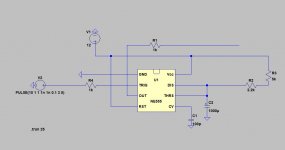
The current delay circuit will only capture first active low pulse and ignoring the rest pulses until it back to state again before you can start triggering the next delay cycle.
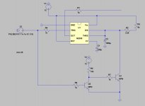
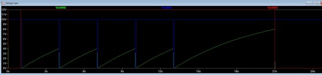
I have modified the circuit as delay2.jpg , it doesn't works that well because my input source is a non rail-rail opamp, it hardly turn off the Q2 and turn on the Q1 to sink the current. I tried using a zener diode before R6 as a threshold to overcome the non-rail-rail output from opamp to turn off the Q2 completely.
I would like to know is there any simpler 555 delay circuit to achieve the delay2 output?
Hi all
I am stuck in generating a delay circuit with an input with multiple pulses.
The current delay circuit will only capture first active low pulse and ignoring the rest pulses until it back to state again before you can start triggering the next delay cycle.
I have modified the circuit as delay2.jpg , it doesn't works that well because my input source is a non rail-rail opamp, it hardly turn off the Q2 and turn on the Q1 to sink the current. I tried using a zener diode before R6 as a threshold to overcome the non-rail-rail output from opamp to turn off the Q2 completely.
I would like to know is there any simpler 555 delay circuit to achieve the delay2 output?
Attachments
TA DA! Thanks everyone for all the help and especially the patience. I deleted everything and started from scratch. When you do something thirty, forty times eventually you get it right after exhausting all the possible mistakes.
Attachments
Last edited:
LTSpice puzzle
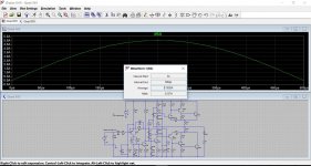
I am a relative novice with LTSpice, and I may not understand how it does "averaging" of waveforms (ctrl+left-click on waveform label). Can anyone help me understand the result I'm getting in the attached screenshot? This a measurement of average of a 5A pk-pk sinewave at the 8ohm LS load of an amplifier simulation - 39mA where I would have expected about 1.5A (i.e. 2.5A pk x 0.63. Is there something I'm not understanding?
I am a relative novice with LTSpice, and I may not understand how it does "averaging" of waveforms (ctrl+left-click on waveform label). Can anyone help me understand the result I'm getting in the attached screenshot? This a measurement of average of a 5A pk-pk sinewave at the 8ohm LS load of an amplifier simulation - 39mA where I would have expected about 1.5A (i.e. 2.5A pk x 0.63. Is there something I'm not understanding?
Attachments
Multiplying by 0.63 applies to the peak value (one half of the sine) For 360 degrees of the waveform, the average is zero. There is as much above as below the notional zero point.
Any repeating regular waveform such as sine or square has an average of zero and so we calculate over half a cycle.
Any repeating regular waveform such as sine or square has an average of zero and so we calculate over half a cycle.
- Home
- Design & Build
- Software Tools
- Installing and using LTspice IV (now including LTXVII), From beginner to advanced