Thanks Jan. I'm using Pete Millett's soundcard interface for testing. Output impedance is low. Input impedance is 49.9k. Reducing the simulated output resistance to 49.9k doesn't change the crossover frequency.
Shouldn't the simulation be taking account of the anode impedance of the 12AX7 common cathode driver? I assume that's what you're referring to by "the 'hidden' anode impedance of the filter driver tube".
Regards,
Dave.
Shouldn't the simulation be taking account of the anode impedance of the 12AX7 common cathode driver? I assume that's what you're referring to by "the 'hidden' anode impedance of the filter driver tube".
Regards,
Dave.
Thanks. Certainly worth rechecking.Possibly it's a wiring/component problem with the actual item?
Thanks Jan. I'm using Pete Millett's soundcard interface for testing. Output impedance is low. Input impedance is 49.9k. Reducing the simulated output resistance to 49.9k doesn't change the crossover frequency.
Shouldn't the simulation be taking account of the anode impedance of the 12AX7 common cathode driver? I assume that's what you're referring to by "the 'hidden' anode impedance of the filter driver tube".
Regards,
Dave.
Well if the output impedance of Pete's unit is low, and the output impedance of the tube driving the network is high, there's your difference.
Unless your actual unit uses the same schematic as in the sim, with the same drive tube. That isn't clear to me. How does the actual unit differ from the sim, if it does differ?
Jan
Hi All there
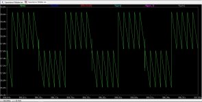
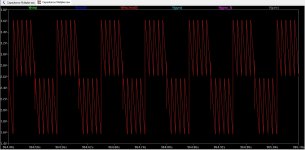
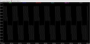
I have try to simulate a class d multilevel version, one is 5 and one is 8 level, just curious about it.
However, the multilevel switching does multiply the carrier frequency, but how then get the bandwidth, I have a postfilter feedback but this depents on the low pass, because mine 350 Khz carrier becomes with 5 level more then 1 Mhz I can set lowpass easely on 250 Khz -3dB I use multiply modulators with fase shifted triangles.
I think I have to follow the triangle carriers, 45 degree shifted, or I need to follow the multiplyed carrier who is high, filter can a lot smaller, even 250 Khz -3dB.
thanks for helping me.
regards.
Attachments

The before question is solved, however, I have two models one is a irs20124 and one is irs2011s.
The irs2011s give defcon errors and does simulate unstable, in first thought I has to duck when defcon 1 occurs, but after I see no danger I did go one, (joke). oke the irs20124 does fine, give a nice output. but the irs2011 does not, unstable.
someone has a good model of the irs2011 chip?.
thanks
The irs2011s give defcon errors and does simulate unstable, in first thought I has to duck when defcon 1 occurs, but after I see no danger I did go one, (joke). oke the irs20124 does fine, give a nice output. but the irs2011 does not, unstable.
someone has a good model of the irs2011 chip?.
thanks
Started reading from the beginning, i.e. from post number #1, dated Anno Domini 2014.
Does the automatic sync thing still work, or is the following paragraph no longer valid?
".....
To manually check for and install updates
1/ Open LT with elevated privileges. In Windows this means right clicking the icon you use to launch the program and selecting the 'run as admin' option.
2/ Under 'Tools' there is a drop-down menu. Select 'Sync release to allow LT to check for and install updates.
When the update is complete the program automatically closes with a message saying the update was successful.
..."
I start it as Admin / privileged user, but keep getting information that upgrade failed. I suppose that this is normal, as this is an unsupported version?
Do you recommend that I skip the "IV" and simply install the XVII ?
It probably makes more sense to put your efforts into XVII tbh.
I am now a 'long term' (as long as posible) XVII user and have no complaints concerning installation and upgrading. There are still many usability wishes but I do not have a real hope that things will improve there. In general, software creators should take a good look at MS's Visual Studio for layout, property editors and usability in general.
Comparing IV to XVII then I will still like the general-interface/usability of IV over (better than) XVII.
Also, even though the point above, I would recommend to use XVII.
Comparing IV to XVII then I will still like the general-interface/usability of IV over (better than) XVII.
Also, even though the point above, I would recommend to use XVII.
Did some reading. Learining. Experimenting. Came up with these results, in hope to modify, better the original circuit (created by Borys, from Poland):
http://iamp.diyaudio.pl/files/capm_v1_1_schematic.pdf
CapM V1.1 - iAMP - DIY way to build Your own amplifier
Here are my files, pictures. Will come back here and add some questions regarding this stuff in an hour or so. Basic questions are:
1). Can I do better?
2). What else in terms of LT functionality would I need / want / wish to test here?
3). What about FFT? Distortion? S/N? How do I approach those areas?
Attachments
-
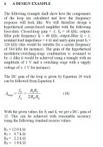
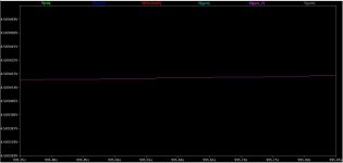
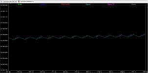
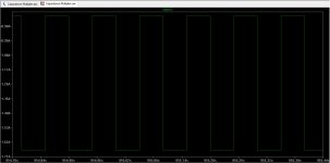
 Capacitance Multiplier - Output Voltage stability - spike.jpg107.7 KB · Views: 56
 -
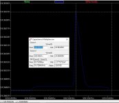
 Capacitance Multiplier - Output Voltage stability - spikes.jpg65.9 KB · Views: 42
 -
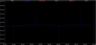
 Capacitance Multiplier - Transient Analysis - Voltages.jpg133.1 KB · Views: 45
 -
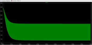
 Capacitance Multiplier - Input Voltage.jpg221.9 KB · Views: 51
 -
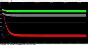
 Capacitance Multiplier - Dropout Voltage.jpg231.1 KB · Views: 98
 -
 Capacitance Multiplier - Gate Voltage.jpg166.7 KB · Views: 102
 -
 Capacitance Multiplier - Gyro2 Voltage.jpg62.1 KB · Views: 100
 -
 Capacitance Multiplier - Gyro1 Voltage.jpg98.2 KB · Views: 114
 -
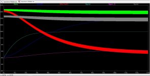 Capacitance Multiplier - First 120 seconds.jpg150.8 KB · Views: 105
 -
Capacitance Multiplier.asc6 KB · Views: 34
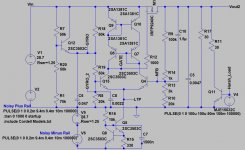
and the circuit schematic ...
I noticed that the simulation to run in full - it takes multiple minutes to finish, or at least to show the stable state. How can I force LT to conduct the simulation quicker? As in: not so much detail, but a quick general presentation of what is going on?
I seem to be blind, or do not see the differences introduced by changing the C10 'speed-up' capacitor. Changed it from 100nF to 1500nF. There "should" be some difference noticeable ... Where best to search for it?
If I were to measure / symulate the S/N, noise rejection ratio (line voltage regulation, load current regulation), is there any method where I could actually put in the "formulas" that calculate such S/N and display the S/N graphically, for example as a function of frequency?
Attachments
Last edited:
Are we all shure LTspice is not leak? because I do not now it somebody do discover that but here, things dissapair from the schematic, as somebody does have control over de pc and change or delete things, I did nver mention it but now I do get on the idea that not me but the program does strange things.
So is suddenly the simulation in error, no outputvoltages and it seems K1 L1 L2 etc was gone, and I did for shure not deleted that from schematic.
I did suddenly also not simulate and seems the ground references where moved and as such not connected anymore, find that is not easy to see, so I think I go see what happens when disconnect internet.
But maybe I get old, so that is why I ask.
regards
... Pro forma: one more thing. in order to open my "Capacitance Multiplier.asc" file,
as posted just recently, you will also need to have the referenced "include" file in the same directory. The file can be downloaded from Bob Cordell's webpage:
http://www.cordellaudio.com/book/Cordell-Models.txt
...
One other thing. "R13+R14" jointly constitute a "trim-potentiometer", at a pre-set position. The trim-pot normally would regulate the amount of drop-out on the series pass device.
I did not know how to present that otherwise.
Too big a dropout - and too much heat would be dissipated on the pass device.
Too small a dropout - and the device falls out of regulation, the gate voltage starts to go crazy, and the output voltage becomes contaminated with noise.
Last edited:
- Home
- Design & Build
- Software Tools
- Installing and using LTspice IV (now including LTXVII), From beginner to advanced