Post your model file and I'll see what I come up with (but no promises).
Good news, I think I've got it working. I renamed the components to something absurdly silly, "ACME2N5457" and "ACME2N5460" to insure that it's picking up the part in the spice directive and not something else. The total THD, harmonic residuals, current through the JFETS and MOSFETS, all look good.
I would not spend any time on this. But I am posting the file just to pass the info along, who knows, it might help somebody else in the future.
And yes, I did download the latest and greatest version XVII. Version IV is still available, I could revert back to that. Either way I still face the learning curve, and would rather learn using most recent, unless there is a compelling reason not to.
Thank you.
Mike
Attachments
Pleased to hear you sussed it out 
It is a learning curve (and then some, lol, I'm still somewhere near the bottom) but its worth it. I've been trying to manage with just LTXVII but there are substantial differences in some areas and so I actually put IV on my system as well. Did that only the other day in fact.
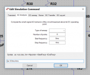
The most annoying aspect is the 'edit simulation' window which carries over settings from one task to the next as here. I'm assured this is 'by design' but I'm really not understanding how it makes life easier. I just don't get it.
It is a learning curve (and then some, lol, I'm still somewhere near the bottom) but its worth it. I've been trying to manage with just LTXVII but there are substantial differences in some areas and so I actually put IV on my system as well. Did that only the other day in fact.
The most annoying aspect is the 'edit simulation' window which carries over settings from one task to the next as here. I'm assured this is 'by design' but I'm really not understanding how it makes life easier. I just don't get it.
Attachments
I'm assured this is 'by design' but I'm really not understanding how it makes life easier. I just don't get it.
Sometimes that might maybe possibly potentially could mean there was no written requirement(s) for the functionality, and the implementation just happened. And it was discovered to be less than ideal later, after final test and release. But rather than go to the expense of changing, testing, and re-releasing, the official party line becomes "works as designed".
 And in the case I've outlined it's not an untruth. But all this is pure speculation on my part, nothing more than my imagination at play: I'm sure does not happen in the real world.
Maybe although the reply I got was that it was a great improvement over LT IV in this regard.
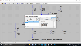
The gist of it is that you right click any .op command on the diagram itself (such as .tran 8ms) and then click cancel it opens to a new window that allows you to right click again and bring up the 'help me edit' option. From there and a flyout menu appears.
That doesn't seem intuitive or quick to me.
although the reply I got was that it was a great improvement over LT IV in this regard.The gist of it is that you right click any .op command on the diagram itself (such as .tran 8ms) and then click cancel it opens to a new window that allows you to right click again and bring up the 'help me edit' option. From there and a flyout menu appears.
That doesn't seem intuitive or quick to me.
Attachments
...That doesn't seem intuitive or quick to me.
I agree, which is why I am still using version IV despite the somewhat better performance of XVII (I am stuck on a 32-bit OS). Much of my SPICE modeling is done on a tablet rather than a "standard" computer, so such issues are even more annoying.
If he were ONLY trying to appeal to users who had been turned off by version IV, then it maybe it could somehow be an improvement?
My computer is dead, but maybe it explains in the user manual how the new interface is to be used?
What we really need is someone who claims to understand the new interface to make a video showing the new workflow.
My computer is dead, but maybe it explains in the user manual how the new interface is to be used?
What we really need is someone who claims to understand the new interface to make a video showing the new workflow.
Hi! Maybe so?I have been asked by another member whether its possible to plot an FFT from a waveform showing a differential voltage.<br />
<br />
I have a simple opamp circuit that seemed a likely candidate to try this on. I've labelled the opamp inputs Vin+ and Vin-. When the sim is run we can left click the + input and place one 'scope probe' on that spot and then still holding the left mouse button move to the - input and place another probe. That gives us a plot of the differential voltage as can be seen.<br />
<br />
How (is it even possible) do we show the FFT of that voltage ?
Attachments
Right click on the name of the differential trace, copy the text. Click on both nodes so you can see their traces. Then do an FFT on that. Then right click on one of the trace names and paste the copied text into it. The waveform viewer is what does the subtraction, not LTspice or the FFT code. So to do a differential FFT you have to FFT both traces and then subtract them. So do an FFT on node1 and node2 and then view V(node1,node2) in the FFT. Which is equivalent to V(node1)-V(node2).
LTspice 'new' from explorer context menu
This is what happens if you have to much time on a Sunday.
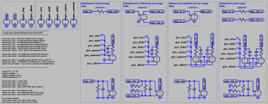
Use the attached files to install a new context item in the explorer context menu. The new file created will not be empty but contains power supplies, generators (sine, square, dvdt, delta and saw-toot) basic settings and more.
There is also (when selecting the balanced out support) a means to consolidate the balanced outputs of your schematic into one signal to analyze. For balance in the model support a generator set that supports the p and n signals from one common source (this (for instance) supports noise or THD measurements including both signal paths).
Default settings for .TRAN, .AC and .NOISE analysis are included.
And, you can specify the simulation speed, from slow to normal and fast (vary the value of the precision parameter).
See the '.txt' file for install information.
There are 4 files attached to this post.
1) FdW's Simulation Base.reg.txt (before using this file, you must remove the '.txt' extension)
2) FdW's Simulation Base Readme.txt
3) FdW's Simulation Base.asc
4) FdW's Simulation Base.png
This is what happens if you have to much time on a Sunday.
Use the attached files to install a new context item in the explorer context menu. The new file created will not be empty but contains power supplies, generators (sine, square, dvdt, delta and saw-toot) basic settings and more.
There is also (when selecting the balanced out support) a means to consolidate the balanced outputs of your schematic into one signal to analyze. For balance in the model support a generator set that supports the p and n signals from one common source (this (for instance) supports noise or THD measurements including both signal paths).
Default settings for .TRAN, .AC and .NOISE analysis are included.
And, you can specify the simulation speed, from slow to normal and fast (vary the value of the precision parameter).
See the '.txt' file for install information.
There are 4 files attached to this post.
1) FdW's Simulation Base.reg.txt (before using this file, you must remove the '.txt' extension)
2) FdW's Simulation Base Readme.txt
3) FdW's Simulation Base.asc
4) FdW's Simulation Base.png
Attachments
Last edited:
The link "WIKI" from the first page (first message) does't work anymore.
Fixed.
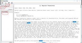
Unfortunately the models don't use simple values (such as hfe and Vce) that we can just input directly to create new ones.
I would strongly recommend you read Bob Cordells book "Designing Audio Power Amplifiers" which has a both a very large section on LTspice and also covers in depth creating and altering models.
If you click on 'Help' in LTspice (located on top line) and then 'Help Topics' and search for 'Gummel' (which in turn will bring up the topic 'Q Bipolar Transistor) you will find a hint of what is involved...
Bobs book is much readable though
Attachments
Unfortunately the models don't use simple values (such as hfe and Vce) that we can just input directly to create new ones.
I would strongly recommend you read Bob Cordells book "Designing Audio Power Amplifiers" which has a both a very large section on LTspice and also covers in depth creating and altering models.
If you click on 'Help' in LTspice (located on top line) and then 'Help Topics' and search for 'Gummel' (which in turn will bring up the topic 'Q Bipolar Transistor) you will find a hint of what is involved...
Bobs book is much readable though
Thanks
Much appreciated!
- Home
- Design & Build
- Software Tools
- Installing and using LTspice IV (now including LTXVII), From beginner to advanced