Well said Byrtt! (as always).
About target curves, can they be generated in REW alone? I can't remember.
Thanks Pano, think you right we can trick REW a bit using its EQ filters section and first export filter settings as wav and thereafter import that one again to have it exported as frd-file, on the other hand think most baked in filters are limited to 2nd orders slopes.
That said many slopes often can be reached cascade other filters if they available into situation, a known one most probably know of is LR can always be created using two cascaded BW slopes of half the order, for example (BW1+BW1=LR2) (BW2+BW2=LR4) etc.
In below have other cascaded combinations that should work by the book but be aware its my own homemade stuff
 created over time when in need of those corrections:
-------------------------------------------------------------------------------------------------------------------------------------------
Convert LR2 to BW2 add PEQ at slopes frq point +3dB Q0.7071.
-------------------------------------------------------------------------------------------------------------------------------------------
Convert LR4 to BW4 add one PEQ at slopes frq point +4.3dB Q1.31 and another PEQ at slopes frq point -1.3dB Q0.54.
-------------------------------------------------------------------------------------------------------------------------------------------
Convert LR8 to BW8 add one PEQ at slopes frq point -0.7dB Q0.51 and another PEQ at slopes frq point +1.06dB Q0.6
and another PEQ at slopes frq point -1.30dB Q0.9 and another PEQ at slopes frq point +3.8dB Q2.56.
-------------------------------------------------------------------------------------------------------------------------------------------
Convert BW1 to BW2 cascade one more BW1 at slopes frq point and add one PEQ Q0.7071 +3dB at slopes frq point.
-------------------------------------------------------------------------------------------------------------------------------------------
Convert BW2 to BW3 add one BW1 at slopes frq point and add one PEQ at slopes frq point +3dB Q1.0 (0.84).
-------------------------------------------------------------------------------------------------------------------------------------------
Convert LR2 to BES2 add one PEQ at slopes frq point +1.3dB Q0.58 (alternative exchange LR2 with 2 cascaded BW1).
-------------------------------------------------------------------------------------------------------------------------------------------
Thanks for your reply
I just can’t understand why i’m getting different results with different calculators
For example i choose Linkwitz-Riley 2 order 2-way crossover for two 8 ohm speakers with cutoff frequency 800hz and i’m getting different capacitors values for the same configuration on xsim and other online calc
Welcome, can think about it will give different capacitors values if that online calculator expect and use a pure flat impedance for driver load and in XSim you feed it a zma-file with the real world resonance and inductance ripple.
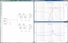
For example in below all component values for LR4 XO point are calculated and taken from the second link into post 518 and works by the book when set up into XSim using its standard textbook flat impedance 8 ohms driver (using no real world zma-file). Suggest you could try setup exactly the same as below and see if it outputs as expected.
Attachments
The difference between XSim and your other program's generated "idealized, imaginary, never-really-correct" crossover circuit could be where it declares the break point. Some use the -3dB point (though the -6dB point is the useful one for a Linkwitz-Reilly). XSim circuit blocks also rounds off values to standardized capacitor values (2%, I think, is used as standard component values in the built-in Circuit Blocks). BTW, you can design your own circuit blocks if you have formulae for the component values of a circuit type. 'File->Change Mode' will let you change to circuit-block design mode. Not easy, but not too hard either.
BTW, a super-easy way to generate an ideal target curve (if you design that way) is to download the beta of XSim3d, and drop a "filter" component between the "power amp" and an ideal (default) "speaker". You can use that to generate LR filter shapes up to 40th order if you want. There are some bugs in XSim3d that still need to be worked on, but most of it along with that filter block work ok. Index of /Xsim/BetaTest
I still wouldn't do that, since even if you design a crossover network to match the curve, you still likely won't have a good finished crossover because of differing delays in the speaker components. Except in the (exceedingly rare) cases where the drivers' reference planes (the effective distances from where each generates sound to your ear) is the same.
Last edited:
No, they're just blocks of circuit components tied to other parameter values (like, say, specify Q and corner frequency instead of specifying the Ls and Cs). They just run the equations to calculate the component values. I don't think there is a LR model in the circuit blocks at the moment.Circuit blocks in xsim are linkwitz-riley based?
The component value selector for parts made with a circuit block moves in 2% standard steps, which is what the circuit block will round to after parameters are configured for. You can change the selector to 5%, 10%, or 20% after "change block to separate parts" if you want more realistic values when tweaking (right-click on the little up/down arrows at the right on the related numeric control).How close you are trying to get to calculated values for capacitors?
If you want more precise component values (which you can enter into component value selectors) you can type them into the Tune component values for an L, R or C and hit enter. Then it won't round to standardized values. But the circuit blocks will always round the values, being intended for engineering rather than mathematical use. The filter curve generator in XSim3D is very precise, though, if you're after textbooks curves to import.
I have a small tool at my site (WinFilters) that will export target curves, but it's only for 2-way. It was just for me to verify that I had the calculations correct for targets, but I decided to put it out as a tool for learning crossover interactions. It uses a right-click context menu.Well said Byrtt! (as always).
About target curves, can they be generated in REW alone? I can't remember.
If you need 3-way, I'm in the process of changes to my main program and can add export of the targets generated in it, including 3-way.
Dave
p.s. Actually, not true 3-way, but it has bandpass for midranges. It doesn't have true 3-way crossovers such as Duelund.
Last edited:
Thank you
And the last question
Which R value do you use?(real or from speaker manufacturer)
My woofer is 8ohm (ae td15m), but measures as 6,3 ohm
Which value shoud i use in crossover?
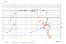
Sorry if i misunderstand but it sounds a bit like you didn't get each driver used into XSim needs in situation data feeded in form of a frd-file (amplitude response) and a zma-file (impedance-curve), else the build in driver into XSim will present your XO network for a flat amplitude response all from DC potential up to light-speed frq's and a impedance curve that is 8 ohms flat all over. Real world drivers amplitude response and impedance is very far from flat all over, as example see below bass driver curves from a manufacture's datasheet where frd-file will be the black green or red trace depending on design axis and the blue curve is presenting zma-file, both will present XSim for the manufactures in situation baffle/cavity/system used.
Free REW software on a computer with a soundcard can help measure impedance in actual situation, also it can measure in situation amplitude/phase domain adding a microphone.
Attachments
Loading problems
Hi
I have installed the software but when I open my comp and the software and open a circuit, it will not open and folling tekst comes up : (file open failed) and (floating point division by Zero)
I am running windows 10
Hope You can help.
Look forward to Your comment.
JP
Hi
I have installed the software but when I open my comp and the software and open a circuit, it will not open and folling tekst comes up : (file open failed) and (floating point division by Zero)
I am running windows 10
Hope You can help.
Look forward to Your comment.
JP
What distance for measurements is the most convenient when making 3way speaker?
Depends on your room. In most domestic rooms, somewhere between 2ft an 4ft (60 and 120 cm) is usually used. Too close, they don't sum correctly, too far and you start measuring room effects instead of the speaker.
Usually for an idea of the bass response, you have to measure the woofer even closer to its cone. In effect, design the crossover with measurements from further back, but to eval the woofer's behavior at lower frequencies, assume it's closer to what you'd see in its very near field. (No one said this was all going to be straightforward)
Most important is having delays adjusted right between drivers. If using a system that locks phase (and you are sure it is behaving like that and the delay you see isn't "wandering"), you can just keep the mic position fixed and use the measurement of each driver as seen. Otherwise use the interference method to align dleays, see Jeff's paper: http://techtalk.parts-express.com/filedata/fetch?id=1149302
Doesn't it feel good calling someone else Geezer
my surname is gezer and i choose this nickname way before i knew what did geezer mean lol
my surname is gezer and i choose this nickname way before i knew what did geezer mean lol
I'm happy to see that you have a great sense of humor!
Crossover tweaking
If I have a finished bi-wired or tri-wired system with crossover can I use xsim to modify the responses in the same way as the original design method?
i.e. use DATS and Omnimic to measure each driver through its own separate crossover components and load the results into xsim, then experiment with additional inductors/capacitors/resistors to modify the response and impedance of the total system.
That would allow the user to build a first crossover, test and trim to get a final result.
- Home
- Design & Build
- Software Tools
- XSim free crossover designer