Thank you for your interest.
What does RF mean? Radio frequencies?
Lets say 500kHz for analog audio purposes would be ok.
100kHz range would be good too - so to start somewhere.
I'm really determined to do this. I've got hundreds of capacitors and spending hundreds of hours making flat impedance response banks - by ear. This is possible, but I'm going gray. I can built any JIG, this is not a problem.
In a earlier post I have a link to a simple Opamp interface that I use to do impedance measurements using my sound card.
In the link there is also some simple software that you use with it.
You can also use this very same interface with REW and Visual Analyzer to do RLC impedance measurements with great accuracy.
I show such examples later in the thread as well.
Here is the post and the link to the interface,
http://www.diyaudio.com/forums/software-tools/212908-exploring-visual-analyser-va-3.html#post3383659
WB6DHW
I hope this helps you.")
jer
In the link there is also some simple software that you use with it.
You can also use this very same interface with REW and Visual Analyzer to do RLC impedance measurements with great accuracy.
I show such examples later in the thread as well.
Here is the post and the link to the interface,
http://www.diyaudio.com/forums/software-tools/212908-exploring-visual-analyser-va-3.html#post3383659
WB6DHW
I hope this helps you.
jer
Thank you Jer it seems lovely tool I just launched it.
Actually I found impedance easiest thing to measure. Used TrueRTA this week.
It requires only two resistors as voltage divider, then I am calibrating input+output system on these resistors. Then I am swaping the lower output resistor to measured impedance (capacitor in this case) and I am getting lovely graphs. Pink noise is doing well for getting live spectrum results. But TrueRTA is not supporting 192kHz sampling soundard, only 96kHz, which gives 10Hz to 48kHz spectrum range. So it's good to observe 1000uF caps or bigger. To analyze smaller caps I need higher frequencies.
it seems lovely tool I just launched it.Actually I found impedance easiest thing to measure. Used TrueRTA this week.
It requires only two resistors as voltage divider, then I am calibrating input+output system on these resistors. Then I am swaping the lower output resistor to measured impedance (capacitor in this case) and I am getting lovely graphs. Pink noise is doing well for getting live spectrum results. But TrueRTA is not supporting 192kHz sampling soundard, only 96kHz, which gives 10Hz to 48kHz spectrum range. So it's good to observe 1000uF caps or bigger. To analyze smaller caps I need higher frequencies.
Last edited:
It is better to use the opamp buffers as this isolate's the sound cards input Impedance ( that also changes with frequency) from the component being measured.
I have been able to measure accurately below 100pf down as low as 1pf by changing the reference resistor using VA.
It may be possible to go below 1pf as well if noise doesn't corrupt the signal.
jer
I have been able to measure accurately below 100pf down as low as 1pf by changing the reference resistor using VA.
It may be possible to go below 1pf as well if noise doesn't corrupt the signal.
jer
Last edited:
I guess you say about HF filtering by low input impedance and parastic capacitances. I didn't get with frequencies that far. Yes, this can be crucial. AD811 could be a good buffer, this is video buffer. Or maybe CA3130, it has over 1Tohm input impedance and good frequency bandwidth.
Last edited:
Yes, they may be good candidates.
I am in the process of building a more permanent fixture myself.
Use an Opamp that will be unity gain stable as I had a few issues with the TL072's breaking into oscillation's every once in a while.
I have some LT1007's that I think I will use, and, I just got a few LM1875's that I am thinking about using for driving speakers and transformer windings and such that needs a little more current to drive properly.
jer
Use an Opamp that will be unity gain stable as I had a few issues with the TL072's breaking into oscillation's every once in a while.
jer
Hi Jer, allow me to recommend the OP07 opamp. Even though it's a Precision Monolithics (now Analog Devices) design, the price is shockingly low: 34 cents in quantity one @ Arrow. Lots of other companies make the OP07 too (just like lots of companies make the Philips/Signetics NE5532 opamp).
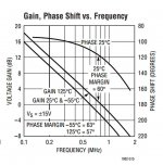
What is great about the OP07 is its enormous phase margin: 80 degrees. See attached image. It is one of the most forgiving, unity-gain-stable opamps around. And cheap too! (Link to price at Arrow)
Attachments

Thanks, I have thought about using the OP07 several times in other projects, but I can't seem to find the Phase Margin rating in either AD's or LT's datasheet's.
However LT's spec sheet does suggest to use a LT1001 or Dual matched LT1002 for improved performance.
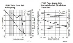
There is a graph on page 6 that shows a 60 degree phase margin for the LT1002,
http://cds.linear.com/docs/en/datasheet/1002fb.pdf
I have some LT1001's but I can also get some LT1002's as well for this project.
Below I have include Phase charts for both the LT1002 and the LT1007.
Thanks for pointing that out to me!!
jer
However LT's spec sheet does suggest to use a LT1001 or Dual matched LT1002 for improved performance.
There is a graph on page 6 that shows a 60 degree phase margin for the LT1002,
http://cds.linear.com/docs/en/datasheet/1002fb.pdf
I have some LT1001's but I can also get some LT1002's as well for this project.
Below I have include Phase charts for both the LT1002 and the LT1007.
Thanks for pointing that out to me!!
jer
Attachments
Last edited:
Ok, I do remember something about that when they came out.
I am just now learning about how Phase margins work.
Which one of the two parts would be best to use in this app?
As I already have both types.
I originally got them to make a jig for very small DC measurements.
I also have some High output current output opamps to drive the DUT's as well for typical usage and I can switch to a current boosted opamp or a chipamp to drive loads that are inductive below 10 ohms to at least .1 ohms and such, rather than my using my big Power amp to drive them.
In my application I am more interested in measuring impedance curves of Step-up transformers for now.
jer
Last edited:
The larger the Phase Margin, the more difficult it is to make the opamp accidentally oscillate. I.e. the more stable in the worst case.
40 degrees of Phase Margin is worrisome, 50 degrees is liveable, 60 degrees is preferable, 70 degrees is delightful, and 80 degrees is un-fwording-believably great. Vigorously clap with both hands and buy the design team a beer. Tell the marketing guy to suck an egg.
40 degrees of Phase Margin is worrisome, 50 degrees is liveable, 60 degrees is preferable, 70 degrees is delightful, and 80 degrees is un-fwording-believably great. Vigorously clap with both hands and buy the design team a beer. Tell the marketing guy to suck an egg.
Isn't this phase margin just low pass filter phase response for frequency? The stronger amplifier filtering, the worse phase response?
And also the biger output capacitance, the worse phase response with frequency?
AD744 is my favourite buffer. But I pay usd 8.
And also the biger output capacitance, the worse phase response with frequency?
AD744 is my favourite buffer. But I pay usd 8.
Last edited:
I am not sure, as I am still studying about this subject.
But, I did know it was critical for a unity gain configuration and gain settings of less than 10 or so.
I just didn't know if a Greater or Lesser Phase Margin was the one to be looking for.
I have decide to use a LT1210 to drive the DUT's as this will give up to 1 amp of driving current and is a very fast Driver chip.
I most likely won't be using anything lower than 10 ohms for my reference resistor nor will I be using any test signals greater than 2v to 4V peak.
Here is the datasheet,
http://cds.linear.com/docs/en/datasheet/1210fa.pdf
Here is another little gem that may interest you, The AD5933 impedance converter,
http://www.analog.com/static/imported-files/data_sheets/AD5933.pdf
It uses the same technique's and it has a 12bit 1MSPS ADC built in to it.
However it does require an MCU with a I2c interface and programming knowledge to use it.
But, It is a cool little chip nevertheless.
I have some of these as well and someday soon I will learn how to work with it.
jer
Last edited:
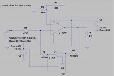
I just finished the design of a suitable unity gain buffer for using a LT1210.
The LT1210 is an incredible little buffer chip and it delivers everything that the spec sheet says it will.
Since my Signal generator can only go to 1Mhz that is the highest that I have been able to test it too.
And, it will deliver that into the 4 ohm load resistor that I am using and with square waves as well!!!
It is rated for as high as 35MHz and it was picking up the signals coming off of my mouse at 27Mhz with ease when it was within a few inches from the protoboard that I have it on right now.
It is also spec at 1.1 amps of current but its maximum as about 2 amps according to the data sheet.
It has the sharpest square waves that I have ever seen an opamp produce as it does have a 900V/us slew rate!
I did employ a LT1007 as a DC Servo to keep the Offset under control of well under 1 mv and better than below .1mv (100uv) with no signal.
Since my meter is not accurate enough to me give such data of that level reliably, by using my scope I have verified such performance.
I have it running off of a +/- 10.2V power supply that I made at of a 16VA wallwart.
It easily produces a 10V p-p signal just before clipping that is ruler flat in to a 4 ohm load resistor, with only the power supply being the limiting factor at this point, clear up to 1Mhz.
It shows a THD of about -90db or .003% across the audio bandwidth.
This is a great little chip and it has been known to be used in a parallled power amplifier design and headphone amplifiers as well.
With the parts I have in the schematic it has a gain of 1 that is matched to within better than, less than +/-2mv at 2.828Vrms at 60Hz measuring frequency.
The 18.64k resistor is the one to be adjusted to match the gain of the circuit.
I used a 15K and a 3.9k in series out of my part bin for the value shown in the schematic.
The data sheet shows to use a .01uf capacitor on the Comp pin.
Since I have no way at this time to measure its performance at that end of the scale( 10-40Mhz) I don't know if it needs it or not.
It makes no difference in the performance of this circuit up to 1 Mhz.
So, the Comp Pin is just left open.
This is a great little amplifier should you need a buffer to be used in testing components with frequency's higher than the audio band.
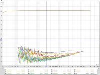
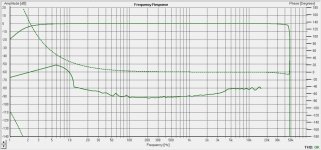
Below have screen shots of its measured performance using REW and HOLMimpulse as well as the schematic and the LTSpice file.
If any one can make any improvements to this I would be very welcomed to see them.
Even Though it is quite impressive as it is, I am going to hook it up to a speaker and a bigger power supply and see how it sounds as well.
Cheers!!!!
jer
P.S. Once I finish this interface, I will present it in its entirety in the "Exploring Visual Analyzer" thread
The LT1210 is an incredible little buffer chip and it delivers everything that the spec sheet says it will.
Since my Signal generator can only go to 1Mhz that is the highest that I have been able to test it too.
And, it will deliver that into the 4 ohm load resistor that I am using and with square waves as well!!!
It is rated for as high as 35MHz and it was picking up the signals coming off of my mouse at 27Mhz with ease when it was within a few inches from the protoboard that I have it on right now.
It is also spec at 1.1 amps of current but its maximum as about 2 amps according to the data sheet.
It has the sharpest square waves that I have ever seen an opamp produce as it does have a 900V/us slew rate!
I did employ a LT1007 as a DC Servo to keep the Offset under control of well under 1 mv and better than below .1mv (100uv) with no signal.
Since my meter is not accurate enough to me give such data of that level reliably, by using my scope I have verified such performance.
I have it running off of a +/- 10.2V power supply that I made at of a 16VA wallwart.
It easily produces a 10V p-p signal just before clipping that is ruler flat in to a 4 ohm load resistor, with only the power supply being the limiting factor at this point, clear up to 1Mhz.
It shows a THD of about -90db or .003% across the audio bandwidth.
This is a great little chip and it has been known to be used in a parallled power amplifier design and headphone amplifiers as well.
With the parts I have in the schematic it has a gain of 1 that is matched to within better than, less than +/-2mv at 2.828Vrms at 60Hz measuring frequency.
The 18.64k resistor is the one to be adjusted to match the gain of the circuit.
I used a 15K and a 3.9k in series out of my part bin for the value shown in the schematic.
The data sheet shows to use a .01uf capacitor on the Comp pin.
Since I have no way at this time to measure its performance at that end of the scale( 10-40Mhz) I don't know if it needs it or not.
It makes no difference in the performance of this circuit up to 1 Mhz.
So, the Comp Pin is just left open.
This is a great little amplifier should you need a buffer to be used in testing components with frequency's higher than the audio band.
Below have screen shots of its measured performance using REW and HOLMimpulse as well as the schematic and the LTSpice file.
If any one can make any improvements to this I would be very welcomed to see them.
Even Though it is quite impressive as it is, I am going to hook it up to a speaker and a bigger power supply and see how it sounds as well.
Cheers!!!!
jer
P.S. Once I finish this interface, I will present it in its entirety in the "Exploring Visual Analyzer" thread
Attachments
Last edited:
I just found this great document from Tektronix that explains the math involved of how to easily find the values of capacitance and inductance using just a scope and a signal generator.
https://www.google.com/url?sa=t&rct...Im9fVrz3rcTwYAhjQ&sig2=wcctWjGpMpKdhoEbSczU7A
Enjoy!
jer
https://www.google.com/url?sa=t&rct...Im9fVrz3rcTwYAhjQ&sig2=wcctWjGpMpKdhoEbSczU7A
Enjoy!
jer
- Status
- This old topic is closed. If you want to reopen this topic, contact a moderator using the "Report Post" button.
- Home
- Design & Build
- Software Tools
- How to measure capacitor impedance graph