Could you please attach the .sch file?
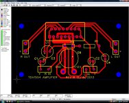
I generated the layout directly from the original schematic in your original post. It was relatively easy to do it on the fly in the PCB layout program since the circuit has few components. I could make the Gerber files available; you could print them using a Gerber viewer program (I use GC-Prevue) and they can be printed to the exact size. The Gerber viewer is a must for anyone doing PCB layouts by computer as a final QC step to make sure your layout will work and/or can be manufactured correctly by a board house.
Also, I have moved the output pads away from the heat sink end of the board per the good advice given above. I did this as a single sided board; it would have been easier to do it as a double sided board since power and ground for U1 could have been on opposite sides of the board and things like the long looping trace from the star point to C4 could have been laid out much better.
I just need to make one board myself now sometime. Probably a good idea for a computer speaker amplifier since my old speakers quit working several months ago and I have been using headphones ever since then.
-Erich