All of the features in this suite of tools are implemented, but I still want to do some additional checking and verification. So this is the final Beta. I would appreciate any help in making sure this program is accurate, reliable and easy to use.
There is a new installation process and the program automatically checks for and downloads newer versions at start-up. I can continue to make changes and you will always have the latest software. If you installed a previous version, you should use Control Panel to uninstall that one first, but that's the last time you will have to do that. The new download link is here:
http://www.audiodevelopers.com/Software/PSD_Lite/setup.exe
The features are summarized below. This program does a lot, and it should satisfy the need for a single integrated tool for Crossover, Baffle, Box and supporting electronics design.
Passive Speaker Designer (PSD) - Lite
Driver Input Module
Configuration/Customization/Help
Crossover Module
Box/Baffle Module
Woofer Box Module
Amp and EQ Module
Integration Environment
There is a new installation process and the program automatically checks for and downloads newer versions at start-up. I can continue to make changes and you will always have the latest software. If you installed a previous version, you should use Control Panel to uninstall that one first, but that's the last time you will have to do that. The new download link is here:
http://www.audiodevelopers.com/Software/PSD_Lite/setup.exe
The features are summarized below. This program does a lot, and it should satisfy the need for a single integrated tool for Crossover, Baffle, Box and supporting electronics design.
Passive Speaker Designer (PSD) - Lite
Driver Input Module
- FRD/ZMA file import
Includes format checking to reject header and trailer data and allows any non-numeric delimiter
Allows browsing web-based directories and directly imports web files - Response Editor tool to browse the FRD/ZMA data, edit individual values, and scale the entire data set.
- FFT-based phase extraction algorithm to ensure measurement data is minimum phase
- Additional Delay tool to add/subtract a fixed delay to the measurement data
- Minimum group delay calculation
Configuration/Customization/Help
- Allows selecting between Single Driver, 2-Way and 3-Way designs
- Configuration used to dynamically configure other menus in the program
- Color customization that is saved with the project data
- Chart customization, including colors, line widths, backgrounds, grid and 3D
- On-line Help files that provide both “how-to” and “how it works” assistance
- Graphics scaling algorithms to resize the windows and chart zoom.
- Printing support for all charts
- Data save routines for most modules to export the data.
Crossover Module
- Schematic-based user entry for intuitive crossover design
- Mouse wheel cycles through common inductor, resistor and capacitor values
- Use of background processing ensures a responsive user interface
- Wide choice of schematic modules to implement nearly any crossover topology
- Tabbed-based driver and chart selections to simplify the interface and ensure usability on laptops
Box/Baffle Module
- Allows drawing cabinet front and side views with up to 20 corners for each view
- Calculates internal volume using external dimensions and wall thickness.
- Calculates driver volume and adjusts the internal volume calculation to account for bracing and port volume
- Calculates driver offsets according to location on the baffle and front baffle angle, and automatically updates the Crossover Module with the offsets
- Uses a ray-tracing algorithm to model Baffle Step and edge diffraction
- Allows modeling open-back cabinets by using additional ray-tracing from the back of the driver
- Multi-threaded design takes advantage of multi-core CPU’s for the ray-tracing
Woofer Box Module
- Models woofer low-frequency response using the accurate Benson model
- Models sealed, vented and passive radiator designs
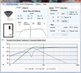
Plots SPL, Excursion, Impedance and Consumed Amplifier Power - Provides a splicing tool to replace the measured response with the more accurate modeled response below a specified frequency
- Provides a “what-if” tab for quickly evaluating various woofer alternatives
- Allows calculating the response of both the woofer and midrange
Amp and EQ Module
- Calculates the effective power from rated power and driver resistance
- Models the system response to a wide range of active filters commonly used for woofers:
Low pass and high pass, up to 8th order
5-band Parametric equalization
Linkwitz Transform
Rumble/boost filters used in subwoofer plate amplifiers - Provides schematic-based interactive tool for calculating component values for the Linkwitz transform and Rumble/boost filters
Integration Environment
- .NET development tools for best compatibility with Windows
- All attributes and key states defined by a Loudspeaker Object Model
Documented in a Help file accessible from the opening menu
Defines the schema for the XML Save/Load file
Supports interoperability with other design tools that use the same object model - Extensible framework that supports both passive and active loudspeaker design
PSD: Superset of PSD-Lite that includes driver, component, and amplifier databases
ASD: Active Speaker Designer for controlling DSP - Driver support for USB interface to control real-time hardware
Allows expansion to address driver and system response measurements
Allows real-time control of DSP for interactive response adjustments
All of the features in this suite of tools are implemented, but I still want to do some additional checking and verification. So this is the final Beta. I would appreciate any help in making sure this program is accurate, reliable and easy to use.
Wow - much easier to use than the Excel version (though I am no expert at that - use Visatons Boxsim quite a bit) - nice features and very intuitive.
One small thing - I think the coloring is backwards here for these graphs? (Vent and Cone output colors swapped in key??)
I just wish there were more FRD and ZMA files available that had PHASE info! THANKS for creating and posting this

(would there be value in adding a function that could generate rough phase info from the TS parms and the Le value just so one can do rough sizings ahead of buying a driver and measuring it oneself?)
Attachments
Wow - much easier to use than the Excel version (though I am no expert at that - use Visatons Boxsim quite a bit) - nice features and very intuitive.
Thanks. I spent a lot of time trying to make it easy to use and "intuitive". I'm glad to hear that others find it easy to use
")
Yep--I'll fix that in the next release. Thanks.One small thing - I think the coloring is backwards here for these graphs? (Vent and Cone output colors swapped in key??)
You can extract the phase from the FRD file by using the Response Editor in the Tools menu. This does what amounts to a Hilbert Transform using a high-resolution FFT (it's a somewhat different algorithm than the Hilbert Transform, but the results are the same). Eventually there will be an Impedance Editor that will do the same for the ZMA data--I just haven't gotten to it.I just wish there were more FRD and ZMA files available that had PHASE info!
Yes--this is the Impedance modeler that is greyed out in the Tools menu. Right now there is no code to do this, but it's on the to-do list. There are a number of good impedance models--I was going to use the one described in a paper by Marshall Leach. The next release will have a very large Thiele-Small database, and it would be nice to have an impedance modeler that could take advantage of it.(would there be value in adding a function that could generate rough phase info from the TS parms and the Le value just so one can do rough sizings ahead of buying a driver and measuring it oneself?)
Also, I was considering Response and Impedance "designers" that would allow you to approximate the response and impedance by using "similar-to" drivers and some graphical tools for tweaking. But I'm not convinced these would be all that useful and decided to wait and see if there was interest in this type of tool.
Is this a bug?
Sort of. I knew about it but hadn't gotten around to fixing it. I just added the code and did a quick test...it should be OK now. Tell me if you find any other issues.
Right now the code is transitioning to integrate a TS database. You can see how it will work if you open the Box Model module and select the "What-if" tab. The "Driver Browse" button will open up an old database that was a snapshot of PE's woofer database from a couple of years ago. I've got the latest drivers from PE and MCM downloaded but need to write some tools to manage the database. Should be pretty cool when it is done.
Back to my speaker building after a summer of working on the house. Just did a design using 1.0.0.0.0 Input was from WT-II for Z and HOLM for SPL. Model got me within a couple of steps of a decent solution pretty quick.
Is the version linked above an update?
Just my 2 cents, there are so many good box modelers out there, the super value here is in the curve fitting for crossover design. All in one tools ( I own a copy of SoundEasy) tend to get out of hand and unwieldy. I would find far more value is more final crossover tweaking, kike driver spacing and offsets, taking a system F and Z with the as built crossover and showing effects on that of tweaks, in addition to the original in-box single driver curves.
Had a thought. It is really easy to twiddle the values and not realize what the Q is. I can see getting in trouble pretty easy. It would be a nifty aid if it calculated and displayed them, maybe with a caution when they get too far out of line. Guess I'll do a spreadsheet for now.
Is the version linked above an update?
Yes--a lot has changed. And it now it checks for updates so the code will always be current. Uninstall the version you have using the Windows Control Panel and then get this new version.
Just my 2 cents, there are so many good box modelers out there, the super value here is in the curve fitting for crossover design. All in one tools ( I own a copy of SoundEasy) tend to get out of hand and unwieldy. I would find far more value is more final crossover tweaking, kike driver spacing and offsets, taking a system F and Z with the as built crossover and showing effects on that of tweaks, in addition to the original in-box single driver curves.
The box model is basically the same that Jeff Bagby used in his WBCD spreadsheet program. It is a very accurate box model using the Benson integrated model (sealed/vented and passive radiator). So it's better than the average box modeler. Originally I wrote the code to show Jeff how he could migrate his spreadsheet to .NET, but that effort never went anywhere. There was even an open source effort for a while, but that fizzled out after a burst of initial enthusiasm. Eventually I finished it off and integrated the code into PSD. However, the Baffle simulator was written from scratch and provides a good multi-threaded ray-tracing model. It has about the same functionality as Edge. So the combination of those two programs is nice. But then add in the Crossover module and the active circuitry model and the program becomes unique.
The program was designed from the beginning to support expansion and new features. The user interface is work-flow driven and all of the menus are very simple and are uniform across the tool suite. So I'm hoping that I've been able to avoid the complexity problems of other all-in-one tools. The feedback that I've gotten suggests that people are finding the program easy-to-use, and I'm finding it easy to add new features. So I think my attention to developing a good software architecture from the beginning has paid off.
Had a thought. It is really easy to twiddle the values and not realize what the Q is. I can see getting in trouble pretty easy. It would be a nifty aid if it calculated and displayed them, maybe with a caution when they get too far out of line. Guess I'll do a spreadsheet for now.
I'm not sure if this really matters. The crossover components interact with the driver transfer function, and all that really matters is the end result. The Q of any isolated individual segment in the chain isn't important--it's the overall system response that matters.
Actually, I'm not a fan of the cascaded filter approach to crossover design. I did it that way in PSD-Lite simply because I wanted to keep the user interface familiar to PCD users. If I made any change to the Crossover module it would be to design an optimizer that calculated the necessary transfer function using a constrained number of poles and zeros. I'll try that some day, but it's not real high on my priority list right now.
Two more comments from me:
1. When I go to "load design", I have to go back into the driver editing and double-click to get the frd/zma files associated with the design to be loaded. Not as bad as having to browse for them again every time like in PCD, but still much less convenient than other programs where everything just loads up.
2. It would be really nice to have the option of displaying output phase and output SPL on the same graph, or at least the same screen. This was one of the best aspects of PCD, I thought. Maybe all the graphs should be able to pop out?
Anyway, nice work on this so far.
Last edited:
Hmmm. Low Q is not really an issue, but high Q might cause some issues you don't see in just the summed response. Much over 1.5 I think I might want to know. I just added a segment for second order electrical to my sheets. First is pretty obvious. Third electrical I need to study as I don't know the equation off the top of my head.
Anyway, Thanks very much for this. It is tons easier to get going than my expensive tool and gets me to the listening/tweaking quite quickly.
Anyway, Thanks very much for this. It is tons easier to get going than my expensive tool and gets me to the listening/tweaking quite quickly.
Two more comments from me:
1. When I go to "load design", I have to go back into the driver editing and double-click to get the frd/zma files associated with the design to be loaded. Not as bad as having to browse for them again every time like in PCD, but still much less convenient than other programs where everything just loads up.
That's on a list of things to do already. I'll implement it once my summer projects are wrapped up.
2. It would be really nice to have the option of displaying output phase and output SPL on the same graph, or at least the same screen. This was one of the best aspects of PCD, I thought. Maybe all the graphs should be able to pop out?.
The full version (PSD-Pro) has a separate module for viewing the system response, and there is more flexibility for showing and hiding the chart data. Some of that approach may get pushed to PSD-Lite--need to think about this.
Thanks.Anyway, nice work on this so far.
But the full version is not something that is available at this point, right?The full version (PSD-Pro) has a separate module for viewing the system response, and there is more flexibility for showing and hiding the chart data. Some of that approach may get pushed to PSD-Lite--need to think about this.
But the full version is not something that is available at this point, right?
right. But software season is coming up
.This summer I ended up doing a lot of work on the house.
Here is a line from REW: 20,291 22,377 25,602
PSD-Lite currently treats commas as delimiters instead of decimal marks--this allows using a comma separated variable (CSV) format. However, someone else already commented on this and when I looked into it I was surprised to find out how many countries outside the US use commas as decimal points (more than those who use the period).
It's an easy fix--I'll make the change in a future release. I'll probably keep support for commas as delimiters as an option.
Very good correlation.
That's good to hear. I've been working on house projects this summer (replacing the wood siding), but I'm anxious to get back to the advanced versions of this program. PSD-Lite is the "core" set of tools that I needed to be working properly, so I'm starting to fell like I'm "done" with those tools and can move on to more interesting (for me, at least) features.
BTW, building your own scaffolding out of 2x4's is not as hard as you might expect--just takes time and some nerve to use it:

- Status
- This old topic is closed. If you want to reopen this topic, contact a moderator using the "Report Post" button.
- Home
- Design & Build
- Software Tools
- PSD-Lite Final Beta