Hi All
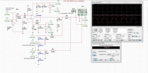
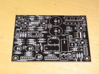
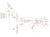
I have drawn a Limp measurement rig with a amp in it, so you can make better measurements on woofers, special the stiff ones.
amp is 10 watt symetrical supply, better current.
PCB come later, when I have time, or maybe someone here can make that.
succes.
I have drawn a Limp measurement rig with a amp in it, so you can make better measurements on woofers, special the stiff ones.
amp is 10 watt symetrical supply, better current.
PCB come later, when I have time, or maybe someone here can make that.
succes.
Attachments
Last edited:
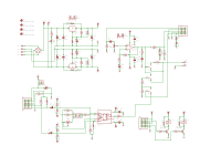
You should employ a unity gain opamp stage to drive the inputs to the sound card.
I have found that the impedance to the sound cards changes with frequency and loads the divider unevenly causing an error across the bandwidth.
It is not as bad using a lower resistance at the bottom of the voltage divider such as a 1k but the error is still there.
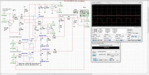
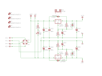
Here is my version as I use a separate power amp.
I have been thinking about adding a smaller chipamp as you have done,
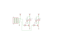
A TEST JIG FOR FINDING ESL STEP-UP TRANSFORMER PARAMETERS
A TEST JIG FOR FINDING ESL STEP-UP TRANSFORMER PARAMETERS
I also take my sample signal for the scope after the buffer as well as the buffer stage compensates for any changes in the impedance and maintains the voltage level that it is taken off of the resistor divider stage.
The buffer has a very high impedance therefore it does not load down the voltage divider.
Cheers !!
jer")
I have found that the impedance to the sound cards changes with frequency and loads the divider unevenly causing an error across the bandwidth.
It is not as bad using a lower resistance at the bottom of the voltage divider such as a 1k but the error is still there.
Here is my version as I use a separate power amp.
I have been thinking about adding a smaller chipamp as you have done,
A TEST JIG FOR FINDING ESL STEP-UP TRANSFORMER PARAMETERS
A TEST JIG FOR FINDING ESL STEP-UP TRANSFORMER PARAMETERS
I also take my sample signal for the scope after the buffer as well as the buffer stage compensates for any changes in the impedance and maintains the voltage level that it is taken off of the resistor divider stage.
The buffer has a very high impedance therefore it does not load down the voltage divider.
Cheers !!
jer
Last edited:
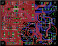
Well I have change it so I can also measure tweeters well, the amp tda is 15 watts, enough for the most heavy speaker measurement with limp.
thanks for thinking with me, here is the corrected schematic, it something is change I hear, and the protection of the opamp inputs I have zeners but maybe two 1N4148 diodes is better, saver 1.2 volts is enough as a measure feedback voltage I gess.
The voltage divider resistors I let intact but I don,t now how opamsp behavior is with low resistance, because of it is fet input I think none.
You do measure transformers and a like, here you need a very stable amplifier, I think it is better to use one discrete who is stable on all loads and special transformers who have big induction, most a very simple power amp will do.
Attachments
Last edited:
Very Good.
I haven't employed any protection diodes yet but I should.
I was using my Crown DC300A to power the transformers.
It works great but it is a bit to big for most of the tests I am doing.
And I get ground loop issues sometimes as it is tied in to my mixer and depending on a certain setting the system will start to oscillate when it shouldn't.
I will eventually solve this by pulling it out of the rack and hooking it up directly but the thing is really heavy and is a beast!!
This can prove to be very dangerous should this happen and I am not using a voltage divider.
I did have a mishap once and I burnt winding because of this.
The thing can supply some current when it is demanded too and a little chipamp would be a little safer in that manner.
Typically the input to the sound cards are good for 5V signal wise and say 15v or so maybe a little more for an overload situation.
If they started to get over voltaged past 5Vp-p they start attenuating the input and output signals signal to nothing at all.
At least that is what I have found with mine.
So far I have measured transformers inductance and capacitance's with a good deal of accuracy.
But I have found that the sound card can't supply enough current in some cases as I have reported in the SimpleS thread when measuring very low impedance loads using low resistance values for the reference resistor.
The opamp has a very high input impedance (10 megohms I think) in that configuration and has a unmeasuerable (for the most part) effect on the 910 ohm resistor.
It acts basically as a current amplifier maintaining the same voltage as the input regardless of the output load impedance(to a certain point of course).
jer
Last edited:
Thanks
Yes your amp don,t need that big, a good current amp is good I thought that elektor has some day a schematic of a simple current amp who can drive high loads, most current but I don,t now if you can use that.
if a soundcard do attenuating the input still get to much before the attenuating circuit give damage, my soundcard is broken one input, I have only the headphone out that day.
Oke, I co further to try to fold a tapped horn, a lot more complicated than a amp, special if I don,t now how yet.
succes.
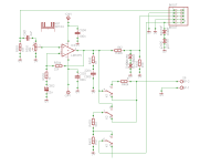
I did sort of the same although I made a complete ARTA box with a microphone preamp and the Power amp as well as all the switching for FR, Impedance and calibration.
Good luck!
Good luck!
Attachments
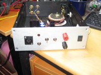
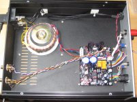
I did sort of the same although I made a complete ARTA box with a microphone preamp and the Power amp as well as all the switching for FR, Impedance and calibration.
Good luck!
Looks very good, have you schematic some bigger?
I have to include supply as well, and maybe I can incl;ude the mike as well, I have the opamps for them but not yet build, maybe I can better build yours as permitted afcourse inventing the wheel again is not needed.
thanks
Sure, here in parts. Please note that I chose 12 V phantom power which works fine with my ECM8000 but a connector for other voltages is included on the PCB.
Attachments
- Status
- This old topic is closed. If you want to reopen this topic, contact a moderator using the "Report Post" button.
- Home
- Design & Build
- Software Tools
- Limp measurement amp.