Eureka !!!!
Finally things are cooperating and coming together!!!
Two things that I have figured out (I think).
1# At the lower end of the frequency scale I forget that the program was displaying the total impedance including the dc resistance of the primary winding.
This was relevant at lower end of the frequency scale and accounted for the .4 to .5 ohms that I thought it was off.
As the frequency rises the capacitive reactance starts to come in into play as well.
Therefore as you start approaching up the slope the value won't be exactly the same as you would get using a pure inductance value,This much I already knew.
2# Using too low of a value for the reference resistor makes for to much of a load on the sound cards output and cause the reference voltage to be lower and droop.
As the frequency gets higher to the impedance peak the reference voltage starts to raise as well and then starts to drop slightly again as it gets over the hump.
This because the sound cards output stage couldn't maintain a constant voltage with the lower value of resistors.
One would think that you would get a more accurate results by using a lower resistor value to use more of the dynamic range of the sound card.
But this won't happen if it cannot drive it properly.
Switching to a 4.7k resistor I got no droop in the reference voltage throughout the sweep and also it resulted in a little higher peak on the curve as well compared to the 1k resistor.
Even with the 1k resistor I was seeing some changes in the level of the reference voltage but they were very small and I couldn't understand why this was and thought that maybe it was written into the program this way.....WRONG!!
I haven't tried a 10K yet as each test takes nearly 20 minutes to do.
Also I increased the settling wait time to 500ms and should go for a full 1s (1000ms) from now on as this will definitely help as well since it takes so long anyhow.
I am thinking about buliding a Class A buffer stage of a few amps to handle measuring the very low resistances that I have planned in the future or maybe just using one of my big power amps to drive the D.U.T.
I will see how this works sometime in the future.
3# As you know the peak of the impedance is the lump of all the RLC values and in this case it is a winding on a transformer.
This peak value was within .03% of what VA2011XE Beta 0.3.2 measured at only a 6Hz difference of the measuring frequency's between the two programs at 8.982Khz using the very same 4.7K resistor.
This difference of .03% also accounts for the .03% shift in the measurement frequency so the results were exactly the same!!!
This is an astonishing figure compared to my earlier tests!!!!
Also both LMSBridge and VA returned the exact same value of inductance so this was a very good indication of things were working properly.
As I was watching the test, I was doing spot calculations with a reactance calculator as well and everything was looking great then too.
Sorry about the confusion as I can just see another poor soul scratching there heads just as I did.
I can say that this program works great with a great deal amount of accuracy as verified by my tests.
And, I wasn't using any special high dollar sound card!!!
Just the little ole' stock Realtek ALC892 worked fine!!!
I can now back track and give my other sound cards another try as I am sure they will work just fine, now that I have found the error of my errors!!! He,he,he,he
My hats off to The programmer(s) for this one!!!

jer")
Finally things are cooperating and coming together!!!
Two things that I have figured out (I think).
1# At the lower end of the frequency scale I forget that the program was displaying the total impedance including the dc resistance of the primary winding.
This was relevant at lower end of the frequency scale and accounted for the .4 to .5 ohms that I thought it was off.
As the frequency rises the capacitive reactance starts to come in into play as well.
Therefore as you start approaching up the slope the value won't be exactly the same as you would get using a pure inductance value,This much I already knew.
2# Using too low of a value for the reference resistor makes for to much of a load on the sound cards output and cause the reference voltage to be lower and droop.
As the frequency gets higher to the impedance peak the reference voltage starts to raise as well and then starts to drop slightly again as it gets over the hump.
This because the sound cards output stage couldn't maintain a constant voltage with the lower value of resistors.
One would think that you would get a more accurate results by using a lower resistor value to use more of the dynamic range of the sound card.
But this won't happen if it cannot drive it properly.
Switching to a 4.7k resistor I got no droop in the reference voltage throughout the sweep and also it resulted in a little higher peak on the curve as well compared to the 1k resistor.
Even with the 1k resistor I was seeing some changes in the level of the reference voltage but they were very small and I couldn't understand why this was and thought that maybe it was written into the program this way.....WRONG!!
I haven't tried a 10K yet as each test takes nearly 20 minutes to do.
Also I increased the settling wait time to 500ms and should go for a full 1s (1000ms) from now on as this will definitely help as well since it takes so long anyhow.
I am thinking about buliding a Class A buffer stage of a few amps to handle measuring the very low resistances that I have planned in the future or maybe just using one of my big power amps to drive the D.U.T.
I will see how this works sometime in the future.
3# As you know the peak of the impedance is the lump of all the RLC values and in this case it is a winding on a transformer.
This peak value was within .03% of what VA2011XE Beta 0.3.2 measured at only a 6Hz difference of the measuring frequency's between the two programs at 8.982Khz using the very same 4.7K resistor.
This difference of .03% also accounts for the .03% shift in the measurement frequency so the results were exactly the same!!!
This is an astonishing figure compared to my earlier tests!!!!
Also both LMSBridge and VA returned the exact same value of inductance so this was a very good indication of things were working properly.
As I was watching the test, I was doing spot calculations with a reactance calculator as well and everything was looking great then too.
Sorry about the confusion as I can just see another poor soul scratching there heads just as I did.
I can say that this program works great with a great deal amount of accuracy as verified by my tests.
And, I wasn't using any special high dollar sound card!!!
Just the little ole' stock Realtek ALC892 worked fine!!!
I can now back track and give my other sound cards another try as I am sure they will work just fine, now that I have found the error of my errors!!! He,he,he,he
My hats off to The programmer(s) for this one!!!
jer
Last edited:
I now have three versions to this program.
In the last tests I was using the original version.
The first update I got two days ago I didn't get any errors at all and the only thing I noticed was a few display errors.
So then I just stuck with the original version.
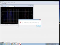
I just installed the very latest version and I get an error at the end of the test run and the program locks up solid.
Here is a screen shot of that error.
Hope this helps.
jer
In the last tests I was using the original version.
The first update I got two days ago I didn't get any errors at all and the only thing I noticed was a few display errors.
So then I just stuck with the original version.
I just installed the very latest version and I get an error at the end of the test run and the program locks up solid.
Here is a screen shot of that error.
Hope this helps.
jer
Attachments
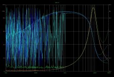
Meanwhile here is one more screenshot of a run of four tests using the original porgram.
I used a 1k,4.7k, 10k and 39k reference resistors in these tests.
With the 1K it did very well.
The 4.7k was alright but you can see noise starting to be introduced into the data at the lower frequency's.
This is from the higher resistance causing too low of a signal to be sampled as it was very near my noise floor of about -100db to -108db at -89db and the impedance of my test part is below 1ohm in this range.
As you can see this just got worse as I tried the 10k (red) and 39k resistors(green).
The peaks stayed generally about the same within 1ohm to .5 ohm of each other except for the 39k resistor test.
But the main part of the slope was the nearly same for all of the tests.
FWIW
jer
Attachments
Last edited:
jer,
You bring up a very good point to remember with both sound card loading and drive. My tests, I have plenty of drive as I am running through a power amp. Most speaker building users will be doing it that way. On the flip side of things, I use a Focusrite 2i2 mic preamp as my sound card. The input impedance is 600 Ohms. So the value of the voltage dividers in the probes and the size of the load resistor are quite important or the high end will be very wrong. This is true on any of these programs using the same concept. I am doing well with 200 Ohm load. My probes are probably still too high. I may drop them to 1K and 500 Ohms. A consumer sound card may have an input as high as 10K, so different values.
This is why I keep telling people "test equipment lies". It doesn't really, but you have to understand what you are measuring. I guess with the fancy modern equipment, they don't teach that in tech school any more. When I learned, we had to remember to add the load from the Simpson 260 to our measurements. No FET inputs in those days!
I Do need to get in touch with Mario but I haven't taken them time yet to do so through his website.
Yes, when I first started with measuring RLC's using VA and LMSBridge I was using a poweramp.
But I was using some voltage dividers so that I didn't blow up the inputs,
(should any strange signal get through from my mixer and fry the inputs to the card) and it was messing up my results for certain ranges.
So then I just used the unity gain buffers to feed the inputs and used the outputs directly from the card and magically all of the programs worked without any errors and the results were finally consistent between them.
Because I am using a transformer that I am testing in a step configuration, setting the gains of all of the stages from the mixer is a PIA and sometimes it would set itself into oscillations for some reason when it shouldn't have.
And it would not be a pretty site with 5KV at 300watts feeding the input to my new computer!!!
Thus the reason for the voltage dividers.
It was one of those situations that caused one of the transformers winding's to burn and short out on me.
Luckily I was able to repair it but it is not in the stock condition as I had received it now.
This was just before you posted the link to this program and was exactly what I was trying to do using the long handed method!!! He,he,he,he
I had seen that link before back when it first came about.
But I never built an interface to use it.
I had actually started looking for it again when you posted it.....Ironic!!!
I used to repair T.V's and I learned a long time ago that if I think the equipment is lying then there is a reason for it!
Except for my cheapy meter that does lie because it doesn't show the same value when I switch ranges!!!
Cheers!!
jer
My uncle was a top electrical engineer at Ford MoCo in Detroit,
And he used to drill Ohms law into me.
I can remember many times how he would come home just Super P.O.ed because of a few fresh out of collage engineers were blowing up $200 and $300 analog meter movements every single day.
Sometimes many in one day because they didn't know how to use Ohms law!!!!
He,he,he,he,he!!!!!
jer
Solution to no display
The values in the registry on install are being set with negative values. So the screen comes up off in space.
You can fix this.
Open regedit
HKEY_LOCAL_MACHINE
SOFTWARE
AcustikA
SmpeS
MainWIndow
Set: ( all values HEX)
LastHeight 212
LastLeft 51
LastState 0
LastTop 3e
LastWidth 37e
ViewStatusbar 1
VIewToolbar 1
Nothing magic about these values, but then the position was ffffsomething, that is a negative number and it does ot exist on the desktop.
Last edited:
Hi
Comparing Impedance peaks from SimpeS to Manufactures Data sheets I get differences between the two, center frequency of the peak can be out by 5-10 HZ sometimes..
My question: Is there something with SimpeS that can cause a shift in the peak center? Maybe something in the way I use the setup?
Thanks
Last edited:
Hi Joel,
to replay your question i've made a comparison using an 8" woofer. First of all i have measured the woofer impedance curve with SimpeS, and then i have compared it with the one on the manufacturer datasheet. As you can see there is considerable differerance of resonance frequency. Now to check the accuracy of SimpeS measurement, i have measured the same woofer with two well known measurement systems: Audiomatica Clio 8.5 and Audio Precision System One.
In the link below the results
http://www.acustika.org/downloads/SimpeS/docs/comparison.pdf
p.s. The measurements were made using release 1.5 of SimpeS and the sine sweep measurement method. SimpeS 1.5 will be released in the next few days.
Thanks for your interest in SimpeS
Mario
There are some new versions Of SimpleS and ASA out !!!
I am going to be giving them a try as soon as they installed!!
AcustikA | signal analysis software tools
jer
I am going to be giving them a try as soon as they installed!!
AcustikA | signal analysis software tools
jer
There are some new versions Of SimpleS and ASA out !!!
I am going to be giving them a try as soon as they installed!!
AcustikA | signal analysis software tools
jer
QuOtE
- Status
- This old topic is closed. If you want to reopen this topic, contact a moderator using the "Report Post" button.
- Home
- Design & Build
- Software Tools
- New speaker impedance tool, SimpeS