I know this is going to sound crazy but… I find the best way to learn about something I know absolutely nothing about, is to write a program about it.
To get my head around how the SPL rolls off based on baffle width, I have decided to write an app that allows me to simulate virtually any baffle shape (flat only at this time).
I know I am probably reinventing the wheel, and there is probably an app already out there that does exactly what I want to do, as I generally find out something exists right after I invent it.
Anyway who knows even if it has been done before I might come up with some new features that no one has tried before. So here goes…
The plan is to design any baffle I want and place the speaker anywhere I want and be able to calculate the frequency it begins to roll off.
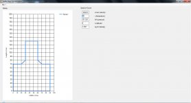
Here is a quick mock-up of what the app might look like. Things like adjustable baffle size, edge points etc. are going to be features, so designing a baffle a 100m long should be doable.
To get my head around how the SPL rolls off based on baffle width, I have decided to write an app that allows me to simulate virtually any baffle shape (flat only at this time).
I know I am probably reinventing the wheel, and there is probably an app already out there that does exactly what I want to do, as I generally find out something exists right after I invent it.
Anyway who knows even if it has been done before I might come up with some new features that no one has tried before. So here goes…
The plan is to design any baffle I want and place the speaker anywhere I want and be able to calculate the frequency it begins to roll off.
Here is a quick mock-up of what the app might look like. Things like adjustable baffle size, edge points etc. are going to be features, so designing a baffle a 100m long should be doable.
Attachments
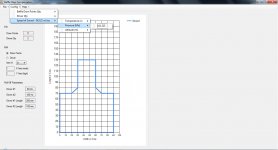
Still putting together some GUI ideas, but for a start I am looking to start with something like this.
The intial baffle points will be defined using two text boxes,but at a later date I will look at possibly sliders or mouse click to position the baffle point.
This is just a framework with little code behind it.
I would like to do an animated radar circle expanding from the driver until it touches the baffle boarder to show the contact point, and give some idea where it is going to touch, but that is probably way down the track.
Attachments
Last edited:
Still putting together some GUI ideas, but for a start I am looking to start with something like this.
The intial baffle points will be defined using two text boxes,but at a later date I will look at possibly sliders or mouse click to position the baffle point.
This is just a framework with little code behind it.
I would like to do an animated radar circle expanding from the driver until it touches the baffle boarder to show the contact point, and give some idea where it is going to touch, but that is probably way down the track.
Wish I had your programming talent! Good luck with your project. I believe EDGE is similar in concept, not sure if there's a radar plot though...
Yes I have played around with Edge before, and it does seem to do a similar kind of thing by virtue of it allows you to place the speakers anywhere on the baffle, but it produces a graph output, where as I am trying to determine baffle size / shape and work out what Hz it rolls off.
I really don’t fully understand the concept of this effect, and I am sure by the time I write the app it will have brought in enough research that the concept sticks in my head whereas just reading a passage about it may not have the same long term effect.
Also I haven’t written anything for a while and I am getting rusty, so I need to get some coding in to brush up. Not sure how I am going to do the radar part just yet but the Graph object in VB gives me enough flexibility to draw up the baffle shape and allow it to be changed dynamically.
I will probably have to overlay the radar part as a separate paint object.
Edit:
Any suggestion / ideas for inclusion are welcome.
Last edited:
Another one that I am aware of is Quarter Wave by Martin King, see Baffle Step Sizing for an overview. Anyway, I think you should start a new thread in the speaker forum (may be the full-range one)? There are some real experts that hang out there. Good luck with your project.
Thanks for that… with a quick look the formula for calculating F3 seems to be consistent with the one I found on the web. Until the other day I didn't even know what F3 was for.
Not sure how far I want to venture down the path of providing information about building correction circuits. At the moment I want to create an app that is more about being an aid to determine the best baffle shape to provide roll off information. Down the track I might want to get involved in the correction side of things.
Have decided this morning that I will use the vertical and horizontal slides in conjunction with the text boxes, as a means to make more detailed changes to the numbers. If I have it update the graph in real time, the text boxes will make the big movements the sliders will make the fine adjustments.
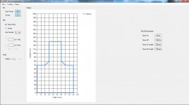
Quick update... Have now coded all the controls on the left of screen dynamically (as apposed to statically popping them on the form).
I prefer to to this so when I resize the screen it is easier to maipulate the size of the controls and move them around.
I have made it so when I change either of the baffle points or driver count it will update the drop down box with the right amount of items.
If the baffle points radio button is checked. the first and last drop down box entries will result in the X & Y coordinate textboxes and slide control being disabled, as the first and last points must be at 0,0 to close off the baffle shape.
I have added a slide control to allow the size of the baffle to be altered, but there is not code behind it other than the code to draw it on the screen.
Here's a progress picture...
Attachments
Last edited:
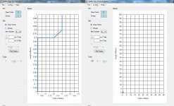
A large part of the graphical side is already completed (easy code)
The tough bit now begins... while I can draw the shape to screen, the values I will be using to measure the distance from the driver location to the nearest boundary will be quite diffacult.
To draw a line I only need to know 2 * X,Y points, but to measure from another point to any point along that line is going to be quite tricky.
I have decided to make the scaling of the baffle non infinate. at 1:1 the baffle will be 1 meter tall by .5 meter wide at 100:1 the biggest baffle possible will be 100 meters tall by 50 meters wide making it big enough to cover even fairly crazy baffle sizes.
Attachments
Just a quick update... progress has been slow as I delve deeper and deeper into 3D graphics. Recently I have been given some fantastic help with 3D graphics to the point where I am now considering making the app load from a graphics file like Sketch Up.
Unfortunately I can't use .skp files as the file format is locked down, but I am looking at a industry standard .3ds file format, Sketch Up Pro allows conversion from .skp to .3ds so there might be some hope yet.
Unfortunately I can't use .skp files as the file format is locked down, but I am looking at a industry standard .3ds file format, Sketch Up Pro allows conversion from .skp to .3ds so there might be some hope yet.
Have to comment, I have not seen mention of Olson or Gedees papers here. AES had quite a few papers on edge diffraction. Step and diffraction are joined at the hip so to speak.
Edge is handy, but it assumes sharp edges. The choice of the pole zero seems to vary from expert to expert. How to model the delay and additional diffraction from rear edges would seem to get really complicated and the Edge models assume a perfectly linear phase from identical perfect drivers. Crack all that, and we will beat a path to your door; asking for free software of course.")
Edge is handy, but it assumes sharp edges. The choice of the pole zero seems to vary from expert to expert. How to model the delay and additional diffraction from rear edges would seem to get really complicated and the Edge models assume a perfectly linear phase from identical perfect drivers. Crack all that, and we will beat a path to your door; asking for free software of course.
The Passive Speaker Designer program in the link includes a BSC/diffraction calculator, and there is a Help file that describes the ray-tracing algorithm. If you can come up with a successful 3D "front-end", I'd be interesting in sharing the BSC number-crunching routines in exchange for a 3D program interface. I'm using VB.NET, and drawing shapes and keeping track of vertices is painful: I'd rather import the data from a decent 3D drawing tool.
In any event, the drawing tools that I've got in the PSD program may give you some more ideas to work with...enjoy.
Passive Speaker Designer (pre-release)
In any event, the drawing tools that I've got in the PSD program may give you some more ideas to work with...enjoy.
Passive Speaker Designer (pre-release)
...What are your intentions for the app?
I've got a "Lite" version of my speaker design tools that is free, and I might add the Baffle Module into that code that at some point. So the Baffle Module might be free, but I haven't decided.
The difficult challenge in these design tools isn't the individual modules such as a crossover designer or BSC calculator--it's getting all the tools to integrate properly. It's hard work to integrate lots of code, and it's difficult to continue working on such a large project without some financial support. So the larger program probably won't be free.
There is a companion program for designing active loudspeakers that will be sold along with hardware.
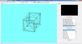
Ok a few things just went wacky in publishing it for the first time, so let me know if it doesn't run.
Have a look and if you think it contains code you could use, let me know and perhaps we can either swap source code or collaborate on something.
This is still only part way finished.
The 3ds object was quickly knocked up using SketchUp, but essentially any drawing app that uses .3ds should load.
Have a look and if you think it contains code you could use, let me know and perhaps we can either swap source code or collaborate on something.
This is still only part way finished.
The 3ds object was quickly knocked up using SketchUp, but essentially any drawing app that uses .3ds should load.
Attachments
Last edited:
Have a look and if you think it contains code you could use, let me know and perhaps we can either swap source code or collaborate on something.
I had played around with some 3D rotation code a long time ago and I know how to make a simple 3D wireframe object and determine the vertices. But what I need is the ability to render a loudspeaker box and to place drivers anywhere on the baffle and be able to determine the baffle edge points. I did that using 2D graphics, with a front and side view, and using the .NET graphics functions. However, what people are really interested in seeing is the ability to import a Sketch-up drawing or something like that and to calculate the baffle diffraction directly from that rendering. So I need to understand how a "object" such as a driver is kept track of in the file and how to calculate the distances from the objects to the edge of the baffle they are attached to.
The other problem I had was calculating the internal volume from the outside points and material thickness. It turns out that following a path inside of a another path at a fixed distance from the outside path isn't an easy math problem. I read about a number of algorithms that do it, but ended up with a fairly simple but elegant solution for my own code. So you can draw a shape with lots of vertices and specify a wood thickness and my code will calculate the location of the inner vertices and then calculate the volume. I know that a good 3D drawing tool will do this...that's another capability I would need.
Well stay tuned over the coming months I plan to do most of that. There are still several obstacles I need to overcome before I get to that stage. First I need to be able to render multiple objects in the same image. In the sample I attached it's a single H baffle and it draws and calculates based that one object, but if I was to have two of them in the same file I need to view both objects as one object from a scaling perspective, otherwise it will base it scaling on the first object.
I had previously done this by refreshing the drawing twice (one to load, second to rescale) but it isn't an optimal way to do it. I am currently working on doing a full multi object rescale before any rendering is done.
I had previously done this by refreshing the drawing twice (one to load, second to rescale) but it isn't an optimal way to do it. I am currently working on doing a full multi object rescale before any rendering is done.
- Status
- This old topic is closed. If you want to reopen this topic, contact a moderator using the "Report Post" button.
- Home
- Design & Build
- Software Tools
- BSC Calculator