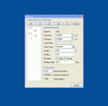
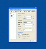
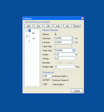
Pete, I think what Guy is asking for is the first program you posted - the one that had the speaker shown in the Geometry View. If you added the selectable measurement units, that would do what about 50% of people need to just work out variations on existing designs to accommodate different drivers. And with variable port placement, it would likely cover 80%.
Me, I'm having a ball trying all the different things I always wished I could do with TLwrx. So, I definitely support your development of the advanced version.
What I miss at this point is an easy way to move the driver away from the end of '0'. Yes, you can construct a model by adding a branch with a bit of math, but then making further adjustments to it is tedious.
Pete, I think what Guy is asking for is the first program you posted - the one that had the speaker shown in the Geometry View. If you added the selectable measurement units, that would do what about 50% of people need to just work out variations on existing designs to accommodate different drivers. And with variable port placement, it would likely cover 80%.
Me, I'm having a ball trying all the different things I always wished I could do with TLwrx. So, I definitely support your development of the advanced version.
What I miss at this point is an easy way to move the driver away from the end of '0'. Yes, you can construct a model by adding a branch with a bit of math, but then making further adjustments to it is tedious.
Yes, I understand that and appreciate it. I think this is what I will aim to incorporate in the program as a basic mode, i just haven't got to that point yet.
I agree about an easy way to move the driver. I'm sure this is possible and would possibly remove the need for a basic mode at all...
Small update today. I have removed the basic mode switch so I can concentrate on making the 'normal' mode work better and easier.
I have also added the ability to change the display angle of each element. When you add new elements it will automatically assign the angle as per previous versions (i.e. alternating between 0 degrees and 90 degrees for each branch).
However, it does enable to change the angle of individual elements so that it looks more normal in the display window. I.e. if you had a '0' and '0.0' element to model an offset TL then you could set '0' element to 0 degrees and '0.0' element to 180 degrees so that both are in a line.
Cool.Small update today. I have removed the basic mode switch so I can concentrate on making the 'normal' mode work better and easier.
Very cool.I have also added the ability to change the display angle of each element. When you add new elements it will automatically assign the angle as per previous versions (i.e. alternating between 0 degrees and 90 degrees for each branch).
Two things seem to have reverted - the Update button no longer functions as an Edit button, and the files are always opening in meters.
I suggest 2 separate programs, one basic, one advanced. That should solve the problem and keep the functionality. But please don't forget to work on variable port placement in basic mode.
I think it's essential for beginners to start in basic mode. If there's no basic mode you are going to lose a lot of people right off the bat.
Presuming the advanced mode includes everything the basic mode has, you only really need the advanced mode if you have sufficient basic instruction on all of the features included.
The problem is with any software, even the basic version can be useless to beginners without adequate instruction.
I have yet to get beyond the installation of this software because I don't have experience with similar programs, so basic or advanced are equally useless at this time.
When a decent help section is included, I am keen to see what this software does.
Please be aware that this software is in development, so any releases posted on the leonardaudio site are 'alpha' releases. That is, everything is subject to change, and there may be crashes and bugs. Hence, writing help files at this time would be a bit premature.
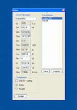
The program comes with a default driver loaded, but likely the first thing one should do is load the parameters of a driver you want to use, and then 'save' it. To do this, go to 'Window' along the top, and then select 'Driver'. Rename 'Default', then enter the driver's parameters in the white fields. Click 'Save', then click 'Update' to see changes in the SPL (and other) graphs. Things will go wacko, as the enclosure isn't meant for the new driver.
BTW, clicking on any of the measurement units will cycle through choices. For instance, you'll probably want to change Vas to liters or cu ft. (Same thing works in the 'Enclosure' window)
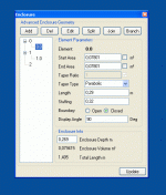
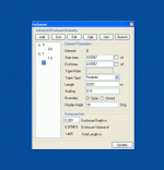
Otherwise, the best approach to become acquainted with the program and TLs is to change the existing parameters, and see what happens. Open the 'Enclosure' window, click on the '0' in the tree window to select it, and then alter the values for the 'Start Area', 'End Area' or 'Length'. Click on 'Edit' to save the changes, then 'Update' to see the results in the graph. If you do this systematically, you'll get a feel for the differences these three things make in TL design. Then you can move on and try 'Stuffing' and 'Taper Type'. These make less of a difference, but can be used to tweak the design.
To start, ignore the squiggles on the right of the SPL display (pipe resonances) and concentrate on getting a smooth, deep, roll-off in the bass.
To try the 'Add', 'Split' and 'Branch' buttons, open the 'Geometry Viewer' window so you can see how they work. They will add or divide to make more elements part of the cabinet. Click on the numbers in tree view to access their values, and again, play with them to see the effects.
HTH....
Last edited:
Thanks for the response above Keriwena. I'd echo those comments.
As for the update button. I had to stop it doing 'edit' as well as it didn't work sensibly in 'basic' mode. I can put it back now.
Also, software 'settings' (Units, graph axis etc.) all get reset to the default upon installing a new update. I'm looking for a way to get around this as its quite annoying.
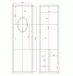
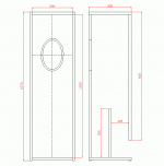
Hi, this is just to check if, finally, I'm doing the right way with the advanced version.
Hopefully will serve as worked example for other people too..
Does not matter if it is a good design or not, but if the fisical object is correctly translated to the program representation.
Included files are: the design dimentions, with the element names pictured in, and the "carpenter" or actual panel cut dimentions, as well as the program project file, ready to run (you must delete the ".doc" part , of course.)
Hope someone can point me If I made mistakes, or if everything is Ok
Many thanks
J
Attachments
Thanks! I'm happy I'm able to use this powerful tool, can do a lot of things, not only transmission lines...
Yes, the dammn commas, nothing works, not PSU designer, nor the Broskie programs, until you learn to use comma nor dot..in my system. Probably this thing is on the instalation basic settings, but I don't dare to mess with Ureliable Uncle Win...
Yes, the dammn commas, nothing works, not PSU designer, nor the Broskie programs, until you learn to use comma nor dot..in my system. Probably this thing is on the instalation basic settings, but I don't dare to mess with Ureliable Uncle Win...
Last edited:
- Home
- Design & Build
- Software Tools
- Transmission Line Modelling Software
