Why not just include it in the filename for the driver then? That's easy enough on your end and nothing in the program needs to change.
I still can't comprehend how you think this info is useful. Besides the 4th order bandpass example I gave there's a couple of other tests you can do to prove this is a meaningless spec at subwoofer frequencies.
1. Take any given driver and design a small baffle OB for it. Check it's output at 20 hz.
2. Take the same driver and design a full size ideal front loaded horn for it tuned to 20 hz. (Hornresp makes this easy with the system design tool.) Check it's output at 20 hz.
The difference in output is going to be enormous.
ok i post this to see if im modeling the way it should.
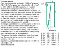
i recreated the Cyborg needle with the W3-871S
i used the sizes as given by the instruction. for easy working i did not fold the line, total line length 184 cm
also attached the working file
rename needle1.txt to needle1.tlp
Am i doing it correctly ?? also if this is the result that looks prety poor , and i listened to the needle a few times and they sound pretty awesome to be honest. whats that HUGE peak way to much lows and allot of crap in the midrange
i also did some designs of my own according to tutorials for mathcad(like rules of thumb). But they in mathcad can work away all the weird peaks from 100 hz to 400. is this some flaw in the mathcad or in this software? because my results look always allot more ragged then theres even if i fidl around allot, and the look of the needle let us see sort of the same result. i will replicate such tutorial with the exact same driver and look what it comes up with. even though i must THANK!!! you allot for all your effort!!!!!!! in making this software !
Attachments
Last edited:
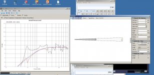
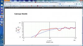
I am trying to learn the use of this software so I checked the model for Cyburgs Needle as practice. I am not an expert so someone with more knowledge may correct what I say
The main difference from my model to yours is the way you have treated the exit of the line . The exit port in yours does not appear at the end of the line.
I have attached a screen grab of my enclosure and the frequency response it gives.
The density of stuffing is not given in the design so I chose the maximum possible density
Attachments
@ just a guy
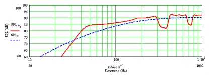
Hi, i do understand about the vendors SPL specs, & realise that they don't always test with the same bandwith etc, & why This was "supposed" to have been sorted out years ago, starting @ 50Hz instead of 100Hz. But some still don't do that.
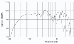
Even so i find it "can" be an ok starting point, as in my screenie. This is a well known respected brand & an expensive 21" driver. Quoted as 97.5dB, 100Hz - 500Hz
Sometimes we need our designs to be Bass/Mid, rather than actual SUB's. So seeing that data is helpful anyway.
Hi, i do understand about the vendors SPL specs, & realise that they don't always test with the same bandwith etc, & why
This was "supposed" to have been sorted out years ago, starting @ 50Hz instead of 100Hz. But some still don't do that. Even so i find it "can" be an ok starting point, as in my screenie. This is a well known respected brand & an expensive 21" driver. Quoted as 97.5dB, 100Hz - 500Hz
Sometimes we need our designs to be Bass/Mid, rather than actual SUB's. So seeing that data is helpful anyway.
Attachments
I am trying to learn the use of this software so I checked the model for Cyburgs Needle as practice. I am not an expert so someone with more knowledge may correct what I say
The main difference from my model to yours is the way you have treated the exit of the line . The exit port in yours does not appear at the end of the line.
I have attached a screen grab of my enclosure and the frequency response it gives.
The density of stuffing is not given in the design so I chose the maximum possible density
i think ur line is way longer as well. it loking better but still kinda crap compared to the sims i see from people using mathcad sheets from King. what i wonder is whos right and whos wrong. i mean if this raggged look would eb real life, i think its not even usable for a 2 way, maybe only a 3 or even 4 way. i mean above 100hertz the graph looks like bad already
i think ur line is way longer as well. it loking better but still kinda crap compared to the sims i see from people using mathcad sheets from King.
I checked my model. The length is almost the same as yours but your area at the wide end is 181cm^2 and mine is 154cm^2.
I found a MJ King mathcad simulation on another forum . It is much smoother but it has big dips between 300-400Hz and 700-800Hz.
I am not sure why the two programs give different results
Attachments
WRT accuracy, Bob Brines and others have posted comparisons to show that MJK's software does quite well. Ditto Augspurger's and AkAbak.
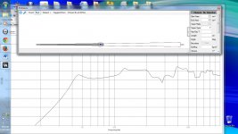
FWIW, here's the sim I did of the TB W3-871S Needles with 0.5 lbs/ft^3 stuffing density from the closed end up to the driver back when it was first posted on DIYaudio. Considering how far below Fs it's tuned, +/- 3dB all the way down to ~45 Hz is quite good.
GM
FWIW, here's the sim I did of the TB W3-871S Needles with 0.5 lbs/ft^3 stuffing density from the closed end up to the driver back when it was first posted on DIYaudio. Considering how far below Fs it's tuned, +/- 3dB all the way down to ~45 Hz is quite good.
GM
Attachments
i recreated the Cyborg needle with the W3-871S
whats that HUGE peak way to much lows and allot of crap in the midrange
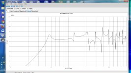
Undamped, a resonant pipe is mostly just a mass of peaks, nulls and a mass loaded one [vented] is even worse since the vent has its own resonant structure to complicate it.
Anyway, mine undamped has a similar resonant structure except its phasing is quite a bit different, though no clue why it would be, but lacking any more info I'm going to assume that MJK's is the more correct of the two.
GM
Attachments
![TB W3-871S Cyburgs-Needle sim [undamped].gif](/community/data/attachments/359/359093-a3ddb1a2413d88e118a1b536bef42400.jpg)
Most drivers have a rising rate suspension, so Xmech [Xlim] can be considerably more than its Xmax, though no clue about much this one will 'stretch' before it takes high power to actually drive it to bottoming out. VCs use to overheat first, but the high temp glues available today may allow them to handle 2-3x their rated power before popping. Only one way to know for sure.........
GM
GM
Most drivers have a rising rate suspension, so Xmech [Xlim] can be considerably more than its Xmax, though no clue about much this one will 'stretch' before it takes high power to actually drive it to bottoming out. VCs use to overheat first, but the high temp glues available today may allow them to handle 2-3x their rated power before popping. Only one way to know for sure.........
GM
Heh so true, keep a close eye while turning it up. Wife thought I was nuts when asking her to measure the displacement while I depressed the cone to measure unspecified Xlim. Was happy it was at least double Xmax (6mm), gets her involved with the process
Yes could have made a jig, but why miss out on all the family fun
I am soooo sure she likes to be involved!
I've been fortunate in that I've never had any of the SAF/WAF issues others have/had to endure and all helped me when asked regardless of the project, with only one setting any conditions. She made it plain from the get-go that she'd help with anything that didn't put her meticulously maintained nails in harm's way.
Indeed, I relied heavily on their generally keener hearing to 'voice' driver tweaks and finished speakers and I assume why the speakers I built for others were so well received by their 'better halfs'.
GM
Indeed, I relied heavily on their generally keener hearing to 'voice' driver tweaks and finished speakers and I assume why the speakers I built for others were so well received by their 'better halfs'.
GM
- Home
- Design & Build
- Software Tools
- Transmission Line Modelling Software