Pheeeeuwww, i could use some help.
adding drivers ok thats easy. but then. is there one person arou nd that could walk me through with a random driver?
for instance i want to make a sub for my electrostatic speakers. i had these woofer laying around so i want to try and make a tl for it. (iss just to around 400/500 hz) trying to make the woofer fire upward so straight in the line is possible, en then i want to fold the line few times so the speaker does not get to high.
AUDAX AT170G4
Nominale Impedanz :
8 Ohm
SPL 2,83 V/1m : 87.0 dB
Fs :38 Hz
Qts : 0.63
Qes : 0.75
Qms :4.0
Vas : 41 Liter
Xmax : 4.0 +- mm
Rdc :5.7 Ohm
Mms : 10 g
Sd : 133 cm²
well i add this to the program in the driver section.
But then im kind of lost, if i go to enclosure. i see the line? but the circle is that the driver ? from what perspective am i looking like from the side of the tl speaker ? why is the circle on the side of it ?
whats the rear and front ? stuff.
my problem mostly is perspective. i can change parameters until i get a decent frequency response but then i still have no clue what i am looking at. how does this translate in a something wich i can make.
Last edited:
You are looking at the front of the TL. When the circle is at the end and half in, half out of the box, the speaker is actually on the end of the box, not the front. That's what you'd want for what you describe.
The "front" stuff would be for a horn or Karlsen baffle, you can ignore that and just work on the "Back" section.
What you're looking at is a dual taper box from the side. Most people build single taper boxes - they keep three sides straight and just slant one. It doesn't matter as long as the beginning and end areas are the same. (if you build a box with 4 sides tapered, ie, a pyramid, then you should use the "conical" taper.)
You have to work on something a while, back up, go forward, back up, make some changes.... apparently it's not always back to the original, just a jump back in the history.I can't get this to reproduce at my end. Could you describe how/when this happens..
Could really use a longer history, and undo/redo buttons on the Geometry Display.
")
Okay, here is the promised writeup. It's not exactly a tutorial, but it does touch on all of the main controls; reading it through should give a sense of what you can do.
The enclosure geometry editing is done in the window entitled Geometry Display, accessed from the Window>Enclosure menu item.
For a TL, just focus on the Rear model. Front is for modeling a horn where you enclose both sides of the driver.
The picture is not a direct visual representation of the enclosure, but rather it shows how the area changes along the length of a segment of the TL. The initial view shows that the driver (circle) is at the end of the segment. That segment is wider (has more area) at the driver end, narrowing toward the other end.
If you left-click somewhere on that segment, it will select the segment and you will see some red control handles that you can use to adjust its areas and length.
Sometimes you have to click several times; the program is prone to miss clicks. You will know that you have succeeded when the red handles appears.
The square handle on the corner near the start end (initially at top left, above the driver circle) is a control that lets you adjust the start area - when you hover over it the cursor changes to an up-down arrow. If you click and drag on that control, the start area changes. You can see the numerical value of the changing area in the status bar at the bottom of the window. When you release the mouse button, the new area will appear in the "Start Area" box at the right of the window, and the Taper Ratio will change to reflect the new ratio between start and end areas over length.
The similar handle (initially) on the top right adjusts the end area in the same way.
The handle in the left middle, attached to a dotted line that sticks out from the center of the driver circle, lets you rotate the segment. It affects the "Angle" box in the numerical panel on the right. The angle is purely for visual convenience; it does not affect the response calculations.
The handle in the right middle adjusts the length.
You can also adjust those parameters by typing a number in the box at the right. However, the new number will not take effect until you move the text cursor out of the box, either by clicking in a different text box or by typing the TAB key. Typing the ENTER key will *not* do the expected thing.
The check boxes to the right side of the Start Area, End Area, and Taper Ratio boxes let you select which of those three parameters is automatically calculated when one of the other two changes. However, that only affects manually entered parameters - the mouse controls continue to adjust the start and end areas, regardless of which of those boxes is checked.
When you adjust a parameter, the modeled response is automatically updated, as are the "Volume" and "Length" numbers in the Model Info - Rear (or Front) sub-panels. Note that the "Volume" number in the "Element: *" sub-panel is for the selected element only, while the one in the Model Info sub-panel is for the collection of all elements.
The Stuffing number ranges from 0 to some unknown upper limit. 2 is a practical upper limit, representing a heavily-stuffed segment. More on that later...
Now, on to the right mouse button ...
If you right-click on an element (you may have to do it several times, per the aforementioned click loss), you will get a drop-down menu that lets to make new segments. The choices are:
Insert Element: Creates a new element to the right of the currently-selected one, and automatically selects the new element so you can edit it. Note that the Element panel on the right of the window changes name, e.g. to "Element: Rear.1", showing the name of the new element and its parameters. If you deselect all elements (click outside), that panel says "Element: No Selection", and you can change the numbers all you want and nothing useful will happen.
Copy Element: Copies the current element to the clipboard, from which you can later paste it.
Paste Element: Pastes the previously-copied element into the model. There is a submenu where you can select where to put it, either before (to the left of) the current element, after it, or as a branch. More on branches later.
Delete Element: Deletes the current element from the model, moving any adjacent elements as necessary.
Add Branch: Creates a new element as a branch off the start side (the left side, unless the element has been rotated) of the current element. Branches let you model designs where the airflow "forks", i.e. has a choice of two directions. They are useful for offsetting the driver so that it is not at the end of the transmission line (create a branch on the first element, to model the portion of the line before the driver). They are also useful for modeling ports, as for bass-reflex cabinets. Typically, after creating a branch, it is common to manually rotate it to visually indicate that it is a branch. Remember that the rotation angle is purely a visual convenience. The element name gets extra dots to show the branching structure. For example, element Rear:4.0 is first element on the branch coming off element number 4. Once you have started a branch, you can add new elements to it, and those new elements can themselves have branches.
Reverse Element: Exchanges the numerical values of the Start and End Areas, without affecting the overall interconnection topology of the model.
Taper: Lets you change the Taper setting (Parabolic, Exponential, Conical) for the element, via a submenu.
Split Element: Splits the current element into two elements, with the same taper, at the midpoint. The line between the two elements is orange, showing that it is a split line. If you then hover on that orange split line when the left element is selected, the cursor changes to show that the split position can be adjusted left or right. (There is a bug, soon to be fixed, whereby the split-adjust function only works right if the model units are in meters.) If you manually adjust a start or end area of an element adjoining the split, the orange line changes to dotted-red, showing that the elements no longer have a consistent taper and thus the split position cannot be adjusted. The line will turn back to orange if you fix the areas so the adjoining elements have consistent taper across the boundary. You can also do this to random adjoining elements - if you make their tapers consistent at the boundary, the join line will turn orange and you can adjust it.
Join Element: Merges two or more adjacent elements with conistent taper into one. This only works if the line between the elements is orange; otherwise it does nothing.
Boundary: Lets you choose, via a submenu, whether the current element's end is open or closed. This only works for the element at the end of the main sequence or an element at the end of a branch sequence.
Stuffing: Lets you choose, via a submenu, either None, Light, Medium, Heavy, or Custom stuffing for the current element. Custom stuffing brings up a dialog box in which you can enter a numerical value. The others chose preset values whose numerical value you can see in the Stuffing field of the Element panel at the right. The element is filled with a gray color whose darkness represents the stuffing density.
If you right-click in the open area outside of the model, you get a submenu with:
Add Rear Element: Creates a new element at the end of the main sequence of the rear model.
Add Front Element: Creates the initial element of the front model if there isn't one already, otherwise creates a new element at the end of the main sequence of the front model.
The units for any numerical value can be changed by clicking on the unit name; repeated clicking will cycle through the available units for that parameter, and the numerical value will change accordingly.
The "Units" tab in the Tools>Settings dialog from the main menu affects the mouse-editing function. For example, if you set the Length unit to Meters and the precision to 0.01, when you use the mouse to adjust an element's length, the length will change in steps of 0.01 m, as shown in the status bar during the mouse drag movement.
In the Geometry Display window, the icons at the top left are:
Arrow in Circle: Clicking on this updates the response calculations.
Wrench: Toggles whether or not the response is auto-updated on every geometry change.
Front: Toggles whether or not the Front elements are displayed.
Rear: Toggles whether or not the Rear elements are displayed.
Oh, and a few other things:
The "Depth" field controls the visual ratio between area and length in the model display. Smaller values make the area more prominent relative to the length (the model appears "fatter"), while larger values de-emphasize the area (model looks "narrower"). It is purely visual.
The model can be panned within the display window by holding down the middle mouse button (or scroll wheel) and dragging. The control used to access this pan function can be changed via Tools>Settings>Mouse from the main menu.
The model view can be zoomed with the mouse scroll wheel (unless the text cursor is inside the Taper Type box, in which case the scroll wheel chooses a taper type).
The Length calculation in the Model Info sub-panels includes all elements including branches.
Thanks WMB !
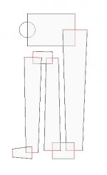
So does This image (in mirror)

Will be sort of the same as my attachment. (only to see if i have the correct perspective ) and this is also how you can create the corners i presume.
one thing dit i moddel the part where the driver is correct like this ? at the beginneing of the Line .
one funny thing is also calculated the volume in liters but what about the corners ? even if i slam in some corner to direct the sound , theres gone be a bigger volume with all those turns ?
So does This image (in mirror)
Will be sort of the same as my attachment. (only to see if i have the correct perspective ) and this is also how you can create the corners i presume.
one thing dit i moddel the part where the driver is correct like this ? at the beginneing of the Line .
one funny thing is also calculated the volume in liters but what about the corners ? even if i slam in some corner to direct the sound , theres gone be a bigger volume with all those turns ?
Attachments
Last edited:
Update [Version 3.6.1.9]
- Split mode is no available whether you have the left or right element selected
- When changing an area, if you hold down Shift then the other area will be the same (Creating a straight element).
- I have added a 'Tapped Horn' feature. If you create a simple tapered horn/TL and then create a split. You can then right click on the element to the right of the split and select "Create 'Tapped Horn'". This will essentially create a Rear enclosure which is a copy of the front enclosure but with the driver at the aforementioned split point. I hope this makes sense. it is similar to how you do a Tapped Horn in HornResp.
The rear enclosure cannot be edited and is linked to the front enclosure. You can click on the TH button to remove the link.
- The Length, Area and Split handles now change their orientation accordingly.
- The number of Undo/Redo steps can be altered in the Settings window. Be warned, changing this will delete all current Undo/Redo history.
- Altered the graphs so that they are re-sized with the main window. The Driver/IB/Terminus/System check boxes now also have an effect on the Displacement and Group Delay graphs. I have also moved Phase to its own tab as I think the SPL is so important it deserves to have a tab to itself.
WrineX,
The corners don't matter as they do in a horn as we're not trying to preserve a coherent waveform through the length of the pipe. You could actually model your cabinet as a simple straight TL and then just fold it during construction, measuring the length down the center of the pipe. Empirical tests have shown this method works well.
The corners don't matter as they do in a horn as we're not trying to preserve a coherent waveform through the length of the pipe. You could actually model your cabinet as a simple straight TL and then just fold it during construction, measuring the length down the center of the pipe. Empirical tests have shown this method works well.
Just a quick guide on how you model Tapped Horns.
We are going to create a tapped horn which is similar to the design below:
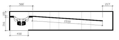
The image below shows the steps to create a simple Tapped Horn.
Start a New Project and open the Geometry Display window.
The default project is a tapered transmission line.
Click on the element and press R. This reverses the element and you now have a horn...
We want to offset the driver. So select the element and press S to split it. Drag the split to around 0.3m.
Select the 1st small element and copy it (Ctrl + C). Then delete it (Del).
Then right click on the remaining element and right click then Paste -> As Branch.
Then select the element you have just pasted and reverse it (R). Spin it round so it looks right.
You now have a horn with an offset driver.
Select the long element and press S to split it again. Drag this split to around 1.7m.
This split point is where we are going to create the 'Tap'.
Right click on the element and select "Create 'Tapped Horn'".
This will copy the enclosure to the front side of the driver with the driver at the point we selected. The two enclosures are linked so making any changes to the enclosure will be made to both 'sides'.
This isn't a great design but hopefully it shows you how a tapped horn can be modelled.
We are going to create a tapped horn which is similar to the design below:
The image below shows the steps to create a simple Tapped Horn.
Start a New Project and open the Geometry Display window.
The default project is a tapered transmission line.
Click on the element and press R. This reverses the element and you now have a horn...
We want to offset the driver. So select the element and press S to split it. Drag the split to around 0.3m.
Select the 1st small element and copy it (Ctrl + C). Then delete it (Del).
Then right click on the remaining element and right click then Paste -> As Branch.
Then select the element you have just pasted and reverse it (R). Spin it round so it looks right.
You now have a horn with an offset driver.
Select the long element and press S to split it again. Drag this split to around 1.7m.
This split point is where we are going to create the 'Tap'.
Right click on the element and select "Create 'Tapped Horn'".
This will copy the enclosure to the front side of the driver with the driver at the point we selected. The two enclosures are linked so making any changes to the enclosure will be made to both 'sides'.
This isn't a great design but hopefully it shows you how a tapped horn can be modelled.
An externally hosted image should be here but it was not working when we last tested it.
An externally hosted image should be here but it was not working when we last tested it.
Hmmm... The error with the Create 'tapped horn' is what happens when you don't have the driver offset.
Can't get driver files from WinISD to work, either.
The "TH" above the display window is counter-intuitive, sitting next to 'Select Front', 'Select Back' buttons. Maybe the letters should be red?
It's "parabolic", not "parabolical".
Buttons for 0, 90, 180, and 270 degrees would be cool.
Can't get driver files from WinISD to work, either.
The "TH" above the display window is counter-intuitive, sitting next to 'Select Front', 'Select Back' buttons. Maybe the letters should be red?
It's "parabolic", not "parabolical".
Buttons for 0, 90, 180, and 270 degrees would be cool.
Argh.. I hate it when you guys get errors that I don't get.
I can do Tapped Horns without an offset driver and also WinISD driver files work for me too..
Do you copy the WinISD files into your driver library? What happens, do they just not appear or don't load properly? do you get an error?
(Cheers for the heads up on 'Parabolical' )
I can do Tapped Horns without an offset driver and also WinISD driver files work for me too..
Do you copy the WinISD files into your driver library? What happens, do they just not appear or don't load properly? do you get an error?
(Cheers for the heads up on 'Parabolical'
)They simply don't appear. I copied them to the folder, renamed them, restarted... none show.
Ah.. Don't rename them.... they need to stay as .wdr files
- Home
- Design & Build
- Software Tools
- Transmission Line Modelling Software