Greetings everyone! I am not sure if this is the forum I should put this in, but since Spice is involved I figured it wouldn't be too out of place!
I've been putting together an audio amp for college project and I've run into a bit of a problem but I am not sure if it's a Spice problem or a design problem. The amp is essentially a booster for MP3 players for small speakers. The output stage is essentially variation of a differential amp, or at least that is what I was taught in the Senior Level Electronics class.
The idea behind the output is that you take 2 AC signals 180 degrees apart and put the load across them hence doubling the Peak-to-Peak voltage. Take a Wall outlet for example. If it's a 110/120v RMS then its roughly 170v to -170V peak to peak. BUT Those voltages are in reference to ground or 0 (Zero) volts... If you had another Wall outlet that was 180 degrees out of phase and you hooked a load across both Wall outlets instead of 0v to 170v for the first half of the sine wave you would get -170 to 170v. One of the lines acts like varying ground to double the voltage you see. This is how some houses get 220/240 RMS outlets.
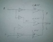
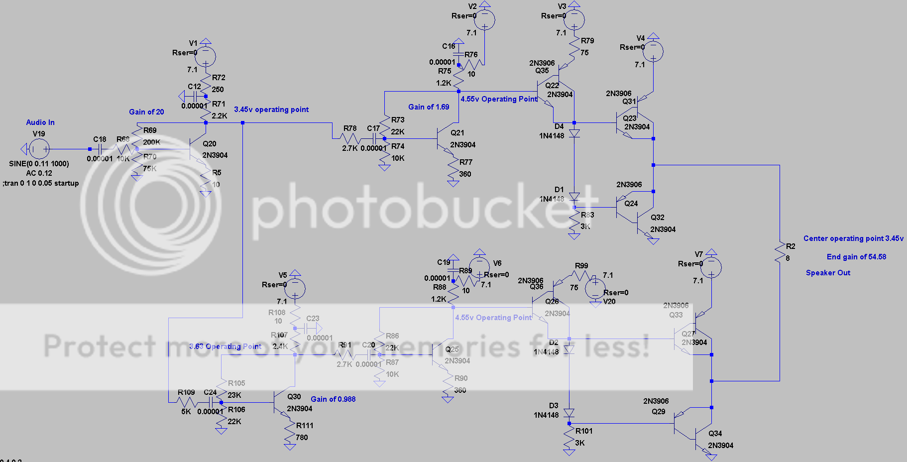
With that in mind here are two amp configurations with almost identical output amplitudes. There is are 180 degree phase difference.
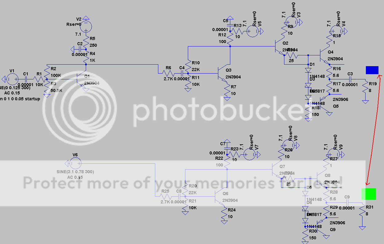
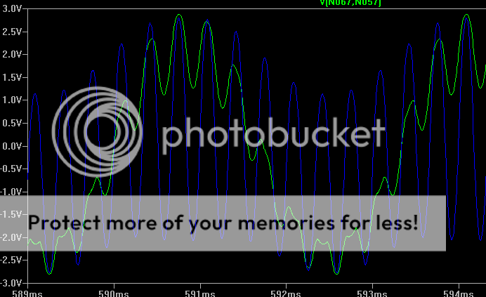
The colors represent what the output waves below are. The Blue color is the upper amp's output before the capacitor and the green color is the lower amp's output before the capacitor. The red line is for the difference between both points.
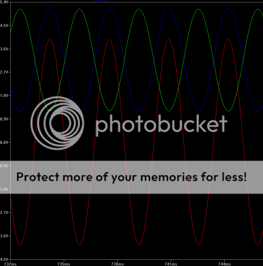
As you can see the voltage swing(peak-to-peak) of each amp by itself is about 4 volts. However, the swing between the two points is 8 volts; double either amp by itself.
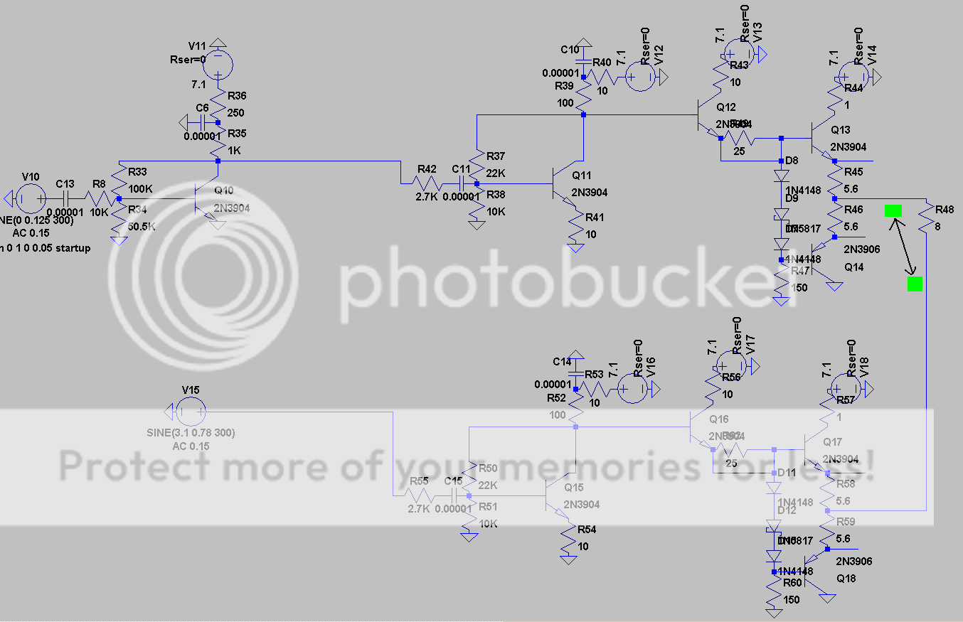
Now, when I connect the load across both amps as shown below, the output swing gets LOWERED down to about 3.2 volts. The Black line between both green blocks represents the two points the voltage is being measured at.
Output:
Why don't I get 8 volts from Peak-to-Peak? Why is the output of the two amps so much lower when they are connected than when they are measured while being connected individualy?
Thanks for your time.
I've been putting together an audio amp for college project and I've run into a bit of a problem but I am not sure if it's a Spice problem or a design problem. The amp is essentially a booster for MP3 players for small speakers. The output stage is essentially variation of a differential amp, or at least that is what I was taught in the Senior Level Electronics class.
The idea behind the output is that you take 2 AC signals 180 degrees apart and put the load across them hence doubling the Peak-to-Peak voltage. Take a Wall outlet for example. If it's a 110/120v RMS then its roughly 170v to -170V peak to peak. BUT Those voltages are in reference to ground or 0 (Zero) volts... If you had another Wall outlet that was 180 degrees out of phase and you hooked a load across both Wall outlets instead of 0v to 170v for the first half of the sine wave you would get -170 to 170v. One of the lines acts like varying ground to double the voltage you see. This is how some houses get 220/240 RMS outlets.
With that in mind here are two amp configurations with almost identical output amplitudes. There is are 180 degree phase difference.
The colors represent what the output waves below are. The Blue color is the upper amp's output before the capacitor and the green color is the lower amp's output before the capacitor. The red line is for the difference between both points.
As you can see the voltage swing(peak-to-peak) of each amp by itself is about 4 volts. However, the swing between the two points is 8 volts; double either amp by itself.
Now, when I connect the load across both amps as shown below, the output swing gets LOWERED down to about 3.2 volts. The Black line between both green blocks represents the two points the voltage is being measured at.
Output:
Why don't I get 8 volts from Peak-to-Peak? Why is the output of the two amps so much lower when they are connected than when they are measured while being connected individualy?
Thanks for your time.
I was actually. I heard they are good up to 500mW and I am looking to get a maximum of 350mW so I figured they should be fine... That and I've never had to pick parts out before so they are literately the only transistor models I know. Kinda like the only OP-Amp I am familiar with is the LM741...
Edit: Holy Hell I think I found the problem. I just noticed the signal loss across the output capacitor is over 95% on the first two amps. I thought AC is supposed to pass through Capacitors unhindered?!
EDIT2: yea it appears you are right I got most of my signal back from changing the 5.6 resistors to 2 Ohm.
EDIT3: FU*&^#$%#&! I was hoping to use this amp for headphones and speakers but it looks like the full bridge model can't work for headphones because headphones use 3 wires. They have a common ground. I don't think this will work if two speakers you are using for 2 sets of these amps have a common ground.
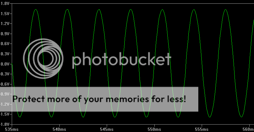
EDIT4: Yea, it definitely won't work with a common ground between the speakers. Here is what happens if you have 2 Amp circuits and the first one has an input at 300 Hertz and the other input is at 3000 hertz:
Back to the drawing board!
Edit: Holy Hell I think I found the problem. I just noticed the signal loss across the output capacitor is over 95% on the first two amps. I thought AC is supposed to pass through Capacitors unhindered?!
EDIT2: yea it appears you are right I got most of my signal back from changing the 5.6 resistors to 2 Ohm.
EDIT3: FU*&^#$%#&! I was hoping to use this amp for headphones and speakers but it looks like the full bridge model can't work for headphones because headphones use 3 wires. They have a common ground. I don't think this will work if two speakers you are using for 2 sets of these amps have a common ground.
EDIT4: Yea, it definitely won't work with a common ground between the speakers. Here is what happens if you have 2 Amp circuits and the first one has an input at 300 Hertz and the other input is at 3000 hertz:
Back to the drawing board!
Last edited:
You had two 8 ohm loads (to ground) first, then replaced those with a single load (floating, not grounded). It should be 16 ohms (two 8 in series) but you made it 8 ohms. It pulled twice the current from the amps, and this reduced the voltage swing, since you have a non-feedback amp topology.
As for the capacitors, you specified "0.00001" which is 10 uF (microFarads). For an 8 ohm load, you should use something like 2200 uF or more. Basically, the impedance of that capacitor must be much less than the impedance of the load (8 Ohm) at the lowest frequency you will use (< 20 Hz), in order to minimize bass roll-off. You know that Z=1/(2*pi*f*C).
(You can specify "10u" instead of "0.00001" in any variant of spice).
(You can specify "10u" instead of "0.00001" in any variant of spice).
Here is the next question; Assuming you have two bridged amps for a stereo audio signal similiar to the one I posted above, there is no common ground for the outputs with the configuration I have. How could you create one? I was potentially thinking of using one of those small audio transformers but the frequency response is pretty bad below 500ish hertz.
Here is the next question; Assuming you have two bridged amps for a stereo audio signal similiar to the one I posted above, there is no common ground for the outputs with the configuration I have. How could you create one? I was potentially thinking of using one of those small audio transformers but the frequency response is pretty bad below 500ish hertz.
You can't.
Short of using a transformer as you suggested, there is no way. You can't have a common connection between the two channels.
It may be possible to use three amps with one being a virtual ground and still have a bridged configuration.
But the virtual ground amp would have to have twice the current handling capability of that of one of the single amp stages.
But this would basically be a waste of circuitry as it would be easier to just increase the power supply voltage in order to get the required voltage swing that you are after.
FWIW
jer")
But the virtual ground amp would have to have twice the current handling capability of that of one of the single amp stages.
But this would basically be a waste of circuitry as it would be easier to just increase the power supply voltage in order to get the required voltage swing that you are after.
FWIW
jer
It may be possible to use three amps with one being a virtual ground and still have a bridged configuration.
But the virtual ground amp would have to have twice the current handling capability of that of one of the single amp stages.
But this would basically be a waste of circuitry as it would be easier to just increase the power supply voltage in order to get the required voltage swing that you are after.
FWIW
jer
Hmm... I may end up trying this if it doesn't murder the efficiency because increasing the Voltage Rail beyond 7.1 is out of the question. The source I am using has high current but is only 0.9 voltage. I already have to use multiple stages of boost converters just to get to 7.1v and the efficiency already suffers pretty badly (67%) because of it. Merely increasing the rail to 7.5v drops the efficiency to 55ish%

Oh boy... That looks like a nightmare with AB amps. Before I get too involved, do they make any small audio transformers (no larger than 12mm in any dimension) with good frequency response in the range of 20 hertz to 20K hertz? The power output would be from 10mW to 500mW. I wouldn't mind using small transformers if I could find decent ones. All the ones I've found have really bad quality outside of like 500~10K hertz
Yes, I have seen them but they are not cheap!
Jensen is one company that comes to mind.
Lundahl is another.
JENSEN TRANSFORMERS, INC. - ISO-MAX® Audio Isolator Products
Lundahl Transformers, audio transformer and tube amplifier transformer manufacturer
Here is a search page from Mouser that may help you,
Transformers Audio & Signal | Mouser
Here is just an example of one of the Jensen transformers,
http://www.jensen-transformers.com/datashts/din2lofl.pdf
And also Sowter,
SOWTER AUDIO TRANSFORMERS
SOWTER PRE AMP/ LINE AMP TRANSFORMERS
Just to name a few.
Jer
Oh boy... That looks like a nightmare with AB amps. Before I get too involved, do they make any small audio transformers (no larger than 12mm in any dimension) with good frequency response in the range of 20 hertz to 20K hertz? The power output would be from 10mW to 500mW. I wouldn't mind using small transformers if I could find decent ones. All the ones I've found have really bad quality outside of like 500~10K hertz
It shouldn't be any more of a problem then your typical BTL configuration except for the higher current handling of the VGamp in which would be just a matter doubling (paralleled) of the output devices.
Also running the VGamp in a Class A mode might be a good idea as well in fact running all three in a Class A mode may not be as efficient but it would guarantee the possibly of a higher sound quality.
FWIW
jer
"guarantee the possib[ilit]y of a higher sound quality"
That sounds like audiophile marketing speak... just shy of making an actual specific claim (by adding wording like "possibility of" to the claim) so that it doesn't need to be proven to be true.
Well from my understanding Class A Amps are the rolls royce of Audio Amplifiers. They provide pretty much supreme quality at the dreaded cost of efficiency. I think I read somewhere that the efficiency could be good if you were driving a signal close to the limit of the amplifier continuously. Otherwise your efficiency will be proportional to the limit of the amp since Class A amps are fully "on" all the time.
I uses the word "possibility" as the term "theoretically".
We already know what Class A mode is and has already been proven to be what it is.
This doesn't mean the a class AB mode amplifier can not produce a good sound quality.
In fact the class AB pushpull amps as in the schematic are already running in a Class A mode as long as the peak current flowing into the load is not more than the quiescent current flowing through the output devices.
If the peak load current exceeds the quiescent current of the output devices then it is considered to be in a Class AB mode unlike Class B because the output devices are never ever in an off state.
The efficiency of a Class A amplifier is quite low typicaly around 10% to 15% and no more than 25%.
But in a push pull Class A or a BTL Class A configuration the efficiency can be as high as 50%.
I suggested that the Virtual ground amp to be running in a Class A mode to help eliminate any crossover switching distortion because it will be spending must of its time near the zero crossing point.
This type of circuit also works with opamps and even they typical have a Class AB output stage.
It has been highly debated in many threads as to whether or not they (opamps) have Class A ,Class AB or Class B output stages and is irrelevant to the overall function of the circuit.
jer
Last edited:
Well from my understanding Class A Amps are the rolls royce of Audio Amplifiers. They provide pretty much supreme quality at the dreaded cost of efficiency. I think I read somewhere that the efficiency could be good if you were driving a signal close to the limit of the amplifier continuously. Otherwise your efficiency will be proportional to the limit of the amp since Class A amps are fully "on" all the time.
I didn't mean to question the statement about class-A amps itself, rather, I was just poking fun at the snake-oil-marketting-like wording that you had used.
Time for some thread necromancy!

So the project that I needed the amp for got OK'd and I've been adjusting the amp design a lot. I've think I got it optimized as much as I can while maintaining minimal cross over distortion.
There is something that has been bothering me though. When I build the amplifier on bread board and test it, I can't draw much more than 630mW of power before the signal starts clipping at both peaks (regardless of load). LT spice shows that I should be able to get around 1284mW (using a 4 Ohm Load in place of the 8 Ohm one) before it starts clipping. I obviously don't expect to get as high as LT spice says I can, but I'd like to at least get 750mW.
The signal going into the AB-amplifiers doesn't drop much or clip with a 4 Ohm load connected, but for some reason the signal is getting lost/reduced and clipped coming out of the AB-stage transistors. I ran through the equations for it several times and it's not matching up with what I am actually seeing.
Any ideas I could try?
- Status
- This old topic is closed. If you want to reopen this topic, contact a moderator using the "Report Post" button.
- Home
- Design & Build
- Software Tools
- Spice problem or Design issue with differential Amplifier