Yes, I've done that and it works well. But I don't remember it letting you test and external sine wave, for example. So I don't think it could measure the tone out of the HP generator.There is a button on the bottom of the window where you can save the .wav, and burn it on CD or so.
I'll have to check on that.
Does VA top out at 96 Khz? I dunno! Don't have anything that will record higher than that.
In the devices control panel, VA shows the result of many differents fs tests/compatibility, and 192kHz is one of them. It prints "yes" or "no" at each fs and bit depht.
The test it seems to perform (you can press a "detect" knob) cannot be seen on my soundcard's control panel.
When RMAA does the test, you can see on the SC panel that it checks all fs.
Didn't find anything in the VA forum, neither english nor italian.
I'm able to read/write italian btw, but do not have the time to translate long text. Short questions I can answer though.
Visual Analyzer Noise
In response to the noise problem Spacecake was having, attached is a screenshot of VA 2011 (not beta) running XP x32 with a low-end, unshielded soundcard. There is nothing plugged into the mic input.
I also tried the beta version which appears to run uover the .NET framework and have found it buggy. I also tried the lone, executable on Linux through Wine..also buggy as expected.
Attachments


Visual Analyser - Oscilloscope
Doubtful it will ever die, but it's difficult to nail down because everyone uses different OSs, sound cards, and even versions of VA.
Doubtful it will ever die, but it's difficult to nail down because everyone uses different OSs, sound cards, and even versions of VA.
Incidentally, sorry all I've gone quiet on the Exploring VA series - I've had to do some work! (It comes up from time to time, as much as I try to avoid it!) But keen to get back to it as soon as I can shrug off my responsibilities.
Terry
Thank you so much for the effort to date on documenting VA. I find your guides very easy to follow, and would very very much appreciate more! I know how much life and work get in the way of our hobbies. I'm hoping this is the case, and that we can look forward to more VA guides in the future (as time permits).
In the mean time, has anyone used VA to test audio amplifiers frequency response and THD? All the tools seem to be there, but I'm not sure how to get meaningful results.
Thanks!
I used VA for many many hours in the last couple of months and overall it is a very good software that mainly suffers from "DIY" syndromes like the inconsistent menus. As for the THD measurement specifically it seems like it is no good. I used an HP distortion analyzer and got very different results. I don't recall the exact figures but around a few hundred % error. Otherwise it's OK.
WoW, I just figured out how to use the ZRLC meter in Visual Analyzer !!!
I used this simple Interface,
WB6DHW
The software for this interface works very good too!!
I have already made a jig for measuring higher voltages of various devices such as transformers and power amplifiers using VA2012XE here,
A TEST JIG FOR FINDING ESL STEP-UP TRANSFORMER PARAMETERS
As well as other types of software using the computers sound card system.
But being able to measure inductive and capacitive values and reactances directly and easily, opens up a whole new world for me.
I have been using VA for a few years now already for THD and frequency response measurement.
This allows me to put to use the boat loads of coils and little rf coils and transformers that I have stocked up that just have part numbers and no cross references to them!!!
Not to mention my interest in ESL transformer design.
And the best part is it didn't cost me a dime and I didn't have to go out and spend $200 or more on a specialized meter.
So far I have even been able to accurately measure capacitance as low as one of my 3pf ceramic disc caps and too a resolution of .1 and .01 of a pf.
And I have measured a few large electrolytic's as well with the same accuracy!!
I have a few hand wound coils that I made that I found that my estimate of their values are quite off according to VA.
So I am in the process whipping up a simple oscillator in order to check them against VA with some known capacitor values and I will report back on my findings.
I have also found that these programs can measure the value of resistors with better accuracy than my cheapy digital meter can.
Providing that you know the exact value of the reference resistor that you are using.
Like I said I have been using VA for a while now, But I am so excited now that I have figured out how to use its full potential !!!!!
My hats off to the guys that wrote these two programs!!!

jer")
I used this simple Interface,
WB6DHW
The software for this interface works very good too!!
I have already made a jig for measuring higher voltages of various devices such as transformers and power amplifiers using VA2012XE here,
A TEST JIG FOR FINDING ESL STEP-UP TRANSFORMER PARAMETERS
As well as other types of software using the computers sound card system.
But being able to measure inductive and capacitive values and reactances directly and easily, opens up a whole new world for me.
I have been using VA for a few years now already for THD and frequency response measurement.
This allows me to put to use the boat loads of coils and little rf coils and transformers that I have stocked up that just have part numbers and no cross references to them!!!
Not to mention my interest in ESL transformer design.
And the best part is it didn't cost me a dime and I didn't have to go out and spend $200 or more on a specialized meter.
So far I have even been able to accurately measure capacitance as low as one of my 3pf ceramic disc caps and too a resolution of .1 and .01 of a pf.
And I have measured a few large electrolytic's as well with the same accuracy!!
I have a few hand wound coils that I made that I found that my estimate of their values are quite off according to VA.
So I am in the process whipping up a simple oscillator in order to check them against VA with some known capacitor values and I will report back on my findings.
I have also found that these programs can measure the value of resistors with better accuracy than my cheapy digital meter can.
Providing that you know the exact value of the reference resistor that you are using.
Like I said I have been using VA for a while now, But I am so excited now that I have figured out how to use its full potential !!!!!
My hats off to the guys that wrote these two programs!!!
jer
Last edited:
I just finished my little test using a armstrong oscillator made out of a BC547 NPN bipolar transistor.
I used the armstrong oscillator circuit to keep any extra parasitic capacitance's at a minimum.
I must say that I am pretty Awed so far with the accuracy of the measurements that were made by VA !!!
I am just guessing better than .1% to .01% or much much better.
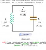
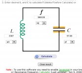
The frequency's with my home made coil of 3305uh ( as measured with VA) were spot on using values of capacitors that where also checked with VA.
With no added capacitance my stray capacitance of my coil and oscillator circuit showed to be about 15pf to 16.5 at 710.1Khz.
Adding in more to the tank cricuit the frequency was spot on within a few 100HZ and no more than 300HZ maximum of error at 256.4Khz with a added 100.5pf and 188.5Khz with a 220pf capacitor that VA said it was about 200 to 205pf or so.
This is including any drift that was occurring as well.
I am completely amazed at this and is a revelation to my bench.
Now I can actually do something more advanced than what I have been doing, now that I have a precise measuring tool instead of sitting here studying the theory as I have been doing the last 35 years!!!
Cheers !!!!
jer
P.S. I am using my motherboards onboard sound system using the Realtek ALC892 set in High definition mode at 192Khz.
I am not sure if it is running in 16bit or 24bit mode as it is set for 16bit and extras and oversampling as well.
It comes up recognizing 24bit but will only run for a little while and then lock up with the ALC 892.
So it is hard to tell, my next venture is to add one of my 24Bit cards and see how it runs.
But, I am quite happy with the way it is now !!!
I used the armstrong oscillator circuit to keep any extra parasitic capacitance's at a minimum.
I must say that I am pretty Awed so far with the accuracy of the measurements that were made by VA !!!
I am just guessing better than .1% to .01% or much much better.
The frequency's with my home made coil of 3305uh ( as measured with VA) were spot on using values of capacitors that where also checked with VA.
With no added capacitance my stray capacitance of my coil and oscillator circuit showed to be about 15pf to 16.5 at 710.1Khz.
Adding in more to the tank cricuit the frequency was spot on within a few 100HZ and no more than 300HZ maximum of error at 256.4Khz with a added 100.5pf and 188.5Khz with a 220pf capacitor that VA said it was about 200 to 205pf or so.
This is including any drift that was occurring as well.
I am completely amazed at this and is a revelation to my bench.
Now I can actually do something more advanced than what I have been doing, now that I have a precise measuring tool instead of sitting here studying the theory as I have been doing the last 35 years!!!
Cheers !!!!
jer
P.S. I am using my motherboards onboard sound system using the Realtek ALC892 set in High definition mode at 192Khz.
I am not sure if it is running in 16bit or 24bit mode as it is set for 16bit and extras and oversampling as well.
It comes up recognizing 24bit but will only run for a little while and then lock up with the ALC 892.
So it is hard to tell, my next venture is to add one of my 24Bit cards and see how it runs.
But, I am quite happy with the way it is now !!!
Last edited:
So I assume you used the ZRLC interface in VA? I tried to use it with the kit that was made by nuova elettronica and I am afraid it was 50% useless. What do I mean? The L,C,Z,R measurements were kind of OK however all the other parameters were junk. Also when trying to measure coils with "high" R (10 Ohms or more) it will go apesh*t.
I have bought a good quality LCR meter for $700 so I can verify the readings of the kit. However VA is a very good program.
Did you try out your board with coils? I am interested to know what you get.
I have bought a good quality LCR meter for $700 so I can verify the readings of the kit. However VA is a very good program.
Did you try out your board with coils? I am interested to know what you get.
Yes, that was the whole point of building the oscillator and that was to check its values.
My coil is a home made coil that I made some years ago.
At first I tried my transformer jig setup because I was using a power amplifier to drive my DUT.
This worked okay for large values but it did not work for the smaller finer values or my home made coil.
So, I removed the resistor dividers and power amplifier and powered the DUT straight from the output of the sound system.
I still used the unity gain buffers to drive the inputs as this isolates the sound systems input impedance from the results of the test.
I am using a TL082 for the buffer.
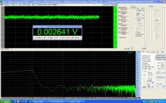
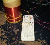
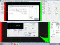
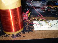
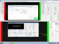
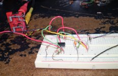
Here are some pictures of my setup and screenshots of the test I just did this very second.
The repeatability is excellent at 3307uh, with only a 2uh difference from my first test early this morning of 3305uh.
The capacitor was right on and the parasitic capacitance of my oscillator did change by 5pf from moving things around.
This is reflected in the calculations as well.
It worked pretty good for me perhaps you can show us the details of your interface and maybe be able to figure out the cause of your errors.
I used a 1k and a 100 ohm resistor for the inductor test at different frequency's and they all returned the same results.
I then used a 1 megohm resistor for very low capacitance values.
Last night my 3pf disc read 2.7 to 3.2 pf and today it read 4.2.
But I will let this slide as nothing is in a box to shield it from stray capacitance's.
The more exact you have your reference resistor value the better the accuracy the results will be.
I failed to do that this time with the 3pf ceramic disc capacitor, But I did it for this test using the 47pf capacitor.
I will be trying many many more samples to make sure that every thing is working properly as well.
Enjoy!!!
My coil is a home made coil that I made some years ago.
At first I tried my transformer jig setup because I was using a power amplifier to drive my DUT.
This worked okay for large values but it did not work for the smaller finer values or my home made coil.
So, I removed the resistor dividers and power amplifier and powered the DUT straight from the output of the sound system.
I still used the unity gain buffers to drive the inputs as this isolates the sound systems input impedance from the results of the test.
I am using a TL082 for the buffer.
Here are some pictures of my setup and screenshots of the test I just did this very second.
The repeatability is excellent at 3307uh, with only a 2uh difference from my first test early this morning of 3305uh.
The capacitor was right on and the parasitic capacitance of my oscillator did change by 5pf from moving things around.
This is reflected in the calculations as well.
It worked pretty good for me perhaps you can show us the details of your interface and maybe be able to figure out the cause of your errors.
I used a 1k and a 100 ohm resistor for the inductor test at different frequency's and they all returned the same results.
I then used a 1 megohm resistor for very low capacitance values.
Last night my 3pf disc read 2.7 to 3.2 pf and today it read 4.2.
But I will let this slide as nothing is in a box to shield it from stray capacitance's.
The more exact you have your reference resistor value the better the accuracy the results will be.
I failed to do that this time with the 3pf ceramic disc capacitor, But I did it for this test using the 47pf capacitor.
I will be trying many many more samples to make sure that every thing is working properly as well.
Enjoy!!!
Attachments
-
 Resonate frequency 47pf.jpg584.7 KB · Views: 143
 -
 Self Resonance.jpg193.3 KB · Views: 134
 -
 Self Resonate Frequency.jpg594.5 KB · Views: 137
 -
 Self Resonane Setup.jpg678.8 KB · Views: 450
 -
 Inducter 3307uh.jpg370.7 KB · Views: 476
 -
 Test Jig Setup Inductor.jpg601 KB · Views: 492
 -
 Capicitor 47pf.jpg368.2 KB · Views: 497
 -
 Test Jig Setup 47pf capacitor.jpg501.6 KB · Views: 602
 -
 Resonance with 47pf.jpg152.5 KB · Views: 137
Last edited:
Yes, it seems to work good!!
However I mad one mistake in my info if you read the other threads that this is the 2011 version and not 2012.
The 2012 version doesn't want to play nice with my sound system at 192Khz.
Sometimes it will work at 24bit as well but will quickly lock up.
I used to use this on some older P4's and had the occasional lockups then quite often.
Not so much on this new FX-6300.
However it is overclocked and I haven't taken the time to make 100% prime95 stable either.
I will try down clocking it to stock sometime and see if that makes a difference with both versions.
jer
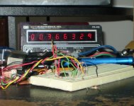
This is my old DUT, when i have used its the accuracy appeared increased by supply it with a dual 17 V 
and the default config in VA
and the default config in VA
An externally hosted image should be here but it was not working when we last tested it.
Last edited:
I have been playing with VA some more.
This time I down clocked My CPU from 4.8Ghz to stock setting at 4.0Ghz.
I don't think that this makes any difference but I just wanted to be sure that the machine is running stable.
It seems that the 2011 version is glitchy as I have had problems with it and they are intermittent.
But actually both of them are glitchy.
When I start the measuring process sometimes I get a pulsed signal instead of a steady tone.
Clicking around and starting and stopping the signal generator (wave function) will sometimes fix itself but not always.
Sometimes when I fire it up it just works perfectly with no issues at all!!!
The 2012 version seems to be more stable but you must start the signal generator function manually and then start the measuring process.
This was confusing at first and is why it took me so long to figure out how to use it, beside building the proper interface.
Also the signal generator window disappears in version 2012 when the RLC window becomes active.
Hopefully this won't be to much of an issue when I finally get the machine set back up with dual monitors.
The other RLCmeter program works quite well and every time I fire it up, but it doesn't have as high of a resolution that VA offers.
I was also able to very accurate low resistances as well!
Even if you don't know exactly what your reference value is you just simply use two resistors and get a base reading and then add your unknown resistance to the bottom grounded resistor and subtract your base value from the new value and you have a very accurate reading of your unknown resistance.
This works great for finding your reference resistor value as well!!
As it is all based upon the ratios and the actual values used are nulled.
I did this to find the value of my home made 1 ohm power resistor that I made out of 35.8 feet of 22ga. twisted pair.
I used a 100ohm for the reference resistor and a 10 ohm on the bottom.
My estimation was about 1.117ohms to 1.135ohms and VA told me that it is 1.145 ohms.
I didn't know the exact length of my cable but I can now start lopping off the end to trim it down to exactly 1 ohm.
I use this resistor to monitor the primary winding currents in my ESL transformer core saturation tests and experiments.
Repeating the earlier tests without paying attention to the Reference resistor the values were still within range by by .4% to 1.5% depending on what resistor I happened to grab out of the pile.
Actually my coil is now reading to be 3372uh instead of 3307 of earlier tests.
I don't know why this is but it is only a 2% difference.
I can say that it is better than no percent of any value at all !!! He,he,he,he
Any how I will keep checking and see if I find an error from my earlier setup as I have moved things around again.
~update!!~ I just found out the difference was caused by anti-phase of the of the 3 turn tickler coil.
With this coil connected in series and and out of phase to the tester my value is now exactly 3306uh as it was before. ~
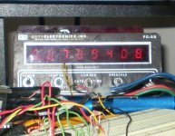
When it is working it shows shows the actual DC resistance values to 1/1000's of an ohm depending on the range.
I thought this was the coolest thing!!!
Anyhow that is my report so far and if I find any more quirps I will surely report them.
One more thing when using either version make sure the your test signal is exactly that as specified in the RLC meter box or else or measured values will be off and/or you will get an over range error and no values at all!!
It would be nice to see a new update soon and maybe these little issues will be fixed!!
Thanks and Good luck!!
jer
This time I down clocked My CPU from 4.8Ghz to stock setting at 4.0Ghz.
I don't think that this makes any difference but I just wanted to be sure that the machine is running stable.
It seems that the 2011 version is glitchy as I have had problems with it and they are intermittent.
But actually both of them are glitchy.
When I start the measuring process sometimes I get a pulsed signal instead of a steady tone.
Clicking around and starting and stopping the signal generator (wave function) will sometimes fix itself but not always.
Sometimes when I fire it up it just works perfectly with no issues at all!!!
The 2012 version seems to be more stable but you must start the signal generator function manually and then start the measuring process.
This was confusing at first and is why it took me so long to figure out how to use it, beside building the proper interface.
Also the signal generator window disappears in version 2012 when the RLC window becomes active.
Hopefully this won't be to much of an issue when I finally get the machine set back up with dual monitors.
The other RLCmeter program works quite well and every time I fire it up, but it doesn't have as high of a resolution that VA offers.
I was also able to very accurate low resistances as well!
Even if you don't know exactly what your reference value is you just simply use two resistors and get a base reading and then add your unknown resistance to the bottom grounded resistor and subtract your base value from the new value and you have a very accurate reading of your unknown resistance.
This works great for finding your reference resistor value as well!!
As it is all based upon the ratios and the actual values used are nulled.
I did this to find the value of my home made 1 ohm power resistor that I made out of 35.8 feet of 22ga. twisted pair.
I used a 100ohm for the reference resistor and a 10 ohm on the bottom.
My estimation was about 1.117ohms to 1.135ohms and VA told me that it is 1.145 ohms.
I didn't know the exact length of my cable but I can now start lopping off the end to trim it down to exactly 1 ohm.
I use this resistor to monitor the primary winding currents in my ESL transformer core saturation tests and experiments.
Repeating the earlier tests without paying attention to the Reference resistor the values were still within range by by .4% to 1.5% depending on what resistor I happened to grab out of the pile.
Actually my coil is now reading to be 3372uh instead of 3307 of earlier tests.
I don't know why this is but it is only a 2% difference.
I can say that it is better than no percent of any value at all !!! He,he,he,he
Any how I will keep checking and see if I find an error from my earlier setup as I have moved things around again.
~update!!~ I just found out the difference was caused by anti-phase of the of the 3 turn tickler coil.
With this coil connected in series and and out of phase to the tester my value is now exactly 3306uh as it was before. ~
When it is working it shows shows the actual DC resistance values to 1/1000's of an ohm depending on the range.
I thought this was the coolest thing!!!
Anyhow that is my report so far and if I find any more quirps I will surely report them.
One more thing when using either version make sure the your test signal is exactly that as specified in the RLC meter box or else or measured values will be off and/or you will get an over range error and no values at all!!
It would be nice to see a new update soon and maybe these little issues will be fixed!!
Thanks and Good luck!!
jer
Last edited:
- Home
- Design & Build
- Software Tools
- Exploring Visual Analyser (VA)