From another post on the TI board seems that this problem is apparent in other settings as well. Someone posted about it (sorry don't have the link right now). The suggestion from TI is to install a special driver which works together with a hardware fix as described in the application note (basically adding a good 3V regulator to power the device. A customer on the board says that is solved the problem. My chip is the PCM2902E model, I am wondering if this fixed in other revisions? I can't find all the suffixes on TI's website.
I suspect that the software referred to is a "filter driver" that happens to work with usb audio kit, rather than driver software for an "audio filter".
A filter driver is one type of driver in the windows driver model (WDM), along with bus and function drivers.
WDM on wikip
If you're thinking this might be fun to program, be warned that it's being supplanted by WDF.......
A filter driver is one type of driver in the windows driver model (WDM), along with bus and function drivers.
WDM on wikip
If you're thinking this might be fun to program, be warned that it's being supplanted by WDF.......
For the 1st time I have something good to update!!!
After going through the forums on TI's website I've noticed that someone solved the noise problem simply be feeding a 3.6V DC into Vccci (pin10) which is the internal analog power supply for the codec.
In the kit this pin is decoupled with a cap to ground. I wanted to check the 3.6V fix but didn't have a regulator and it was around 10PM and I hate to wait for tomorrow so I went through stuff I have and found an evaluation board from microchip and it had a 3.3V regulator. I pulled it out together with all the caps and even a coil and using a thin hookup wire and some hot melt glue I bonded everything onto the kit's PCM2902 PCB and plugged it in. I was shocked!!! This actually did the trick! I will post pictures of my amateurish work later today or tomorrow.
Here we go...
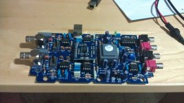
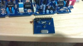
The 1st picture shows the NE PCB with the BB PCM2902E daughter-board in the middle. The 2nd picture shows the regulator (SOT23), 3 caps and 1 inductor. The 3.3V regulator is an MC7100 I think. On the input side there's a 10uF electrolytic cap paralleled with 1uF to ground and a series 10uH inductor. The output side of the regulator has a 1uF cap to ground as well. Output goes to pin10 (Vccci). That's all.
The 1st picture shows the NE PCB with the BB PCM2902E daughter-board in the middle. The 2nd picture shows the regulator (SOT23), 3 caps and 1 inductor. The 3.3V regulator is an MC7100 I think. On the input side there's a 10uF electrolytic cap paralleled with 1uF to ground and a series 10uH inductor. The output side of the regulator has a 1uF cap to ground as well. Output goes to pin10 (Vccci). That's all.
Attachments
Last edited:
Stunning, space-cake. Well done!
It would be good to mention this to Nuova Elettronika and whoever sold you the kit (if it wasn't them). It would seem desirable that this was built into the kit in future.
I'd be interested in hearing how the card works compared to using a normal sound card for this work. What do you see as the advantages?
Terry
Thank you very much for the comments 
It might not be clear from the pictures but the small board came with the kit, this is a daughter board for the PCM2902 that NE uses for a few of their projects (including the ZRLC meter I had so much trouble with - perhaps this is why - it uses the same card).
The regulator "section" came from a Microchip MCP3221 evaluation board, however any good regulator will probably work here. TI suggest their own model in one of the applications on the datasheet.
Regarding NE, I wrote them an email and I hope tomorrow someone will be kind enough to bother to read it. The response I've received for my 1st email was something like: "this kit is great people use to design tube amps". Not a single word on anything specific I wrote them. I have little faith they will do anything with the information. As I said, they use this module in a number of their kits and even though this only means that the small board needs to be populated with a few extra components I do not expect this from someone who did not test (?!?) the kit before selling it. This also brings up the question who buys these kits? Where is everyone? Isn't there at least one other person who saw this post and owns the kit? Very strange...
I will compare the card to my VIA sound card, intended to do that anyway and at least now I'll have some use for the 3.5mm jack to BNC junction box I bothered to make after initially giving up on the NE kit. What I can say at this point without special testing is that the internal sound card suffers from some noise at higher freq., if I remember correctly above 18.5KHz but these are pretty weak so probably won't interfere with measurements too much.
Last edited:
Regarding NE, I wrote them an email and I hope tomorrow someone will be kind enough to bother to read it. The response I've received for my 1st email was something like: "this kit is great people use to design tube amps". Not a single word on anything specific I wrote them. I have little faith they will do anything with the information. As I said, they use this module in a number of their kits and even though this only means that the small board needs to be populated with a few extra components I do not expect this from someone who did not test (?!?) the kit before selling it. This also brings up the question who buys these kits? Where is everyone? Isn't there at least one other person who saw this post and owns the kit? Very strange...
I guess it also reminds us of the divide that language makes. Here we have NE publishing some really interesting stuff (although, as you point out, seeming not to test it very thoroughly!), but we are locked out of it by not speaking Italian. And the presumably many Italians who would have bought and used the kit are probably mostly locked out of DiyAudio by not speaking English.
I will compare the card to my VIA sound card, intended to do that anyway and at least now I'll have some use for the 3.5mm jack to BNC junction box I bothered to make after initially giving up on the NE kit. What I can say at this point without special testing is that the internal sound card suffers from some noise at higher freq., if I remember correctly above 18.5KHz but these are pretty weak so probably won't interfere with measurements too much.
I look forward to hearing the results of your tests! I'm still wondering about building such a card into my proposed control unit to avoid noise pick-up en route to the computer.
It's perhaps surprising that, if they were going to the trouble of designing a special card, they didn't opt for a wider bandwidth than the usual sound card. I'd have like DC to say 48k (bandwidth, so DC coupled and 96k or more sampling speed), just so the limits of the card are well beyond the audio band extremes. But maybe that's just too hard?
Do you know if you can get significantly closer to DC by increasing coupling capacitors, or is there some other limiting factor in the system at the LF end?
Terry
Friday I was playing around with V.A. and an HP 8903B distortion analyzer.
You might have noticed that there is a THD tab in the analyzer section. Using the 8903B as an external source, I got the number to agree between the HP and V.A., sort of. Both said about 0.002% THD if VA was switched to "None" for window smoothing. Anything else and VA reported much lower THD than the HP did. Of course I was using a soundcard for input to VA and the 8903B's own input.
What was also interesting is that the HP 8903B was measuring THD+n when reporting 0.002% and VA had to be in THD (only) mode to get the same number. I know there are some questions and concerns about how software measures THD, so I thought the comparison was interesting to see the two approaches.
FWIW, here is an ARTA spectrum of the HP distortion as seen by my M-Audio card. Orange is the HP signal, green is the M-Audio DAC itself.
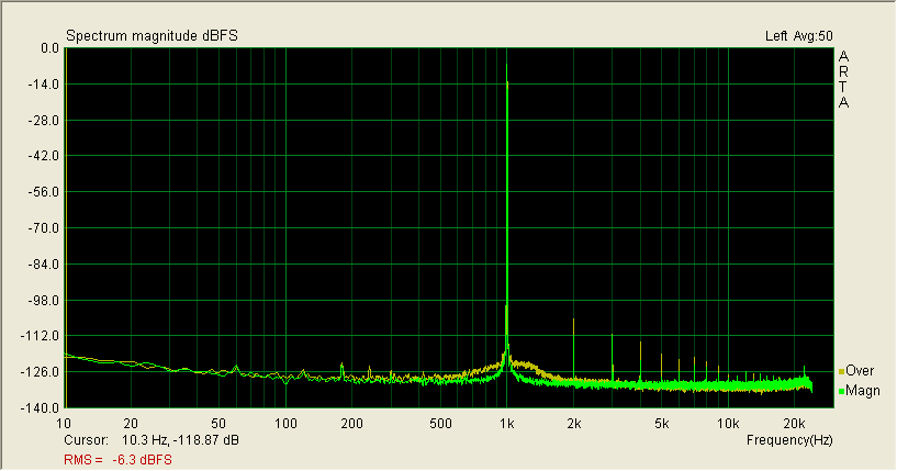
I used ARTA here because it runs faster than VA for FFT plots.
You might have noticed that there is a THD tab in the analyzer section. Using the 8903B as an external source, I got the number to agree between the HP and V.A., sort of. Both said about 0.002% THD if VA was switched to "None" for window smoothing. Anything else and VA reported much lower THD than the HP did. Of course I was using a soundcard for input to VA and the 8903B's own input.
What was also interesting is that the HP 8903B was measuring THD+n when reporting 0.002% and VA had to be in THD (only) mode to get the same number. I know there are some questions and concerns about how software measures THD, so I thought the comparison was interesting to see the two approaches.
FWIW, here is an ARTA spectrum of the HP distortion as seen by my M-Audio card. Orange is the HP signal, green is the M-Audio DAC itself.
I used ARTA here because it runs faster than VA for FFT plots.
Pano, it would be interesting to also compare the two instruments measuring higher levels of distortion. If you put one or a pair of diodes (in parallel but one reversed) across the source output, you can tweak the level for something like a few percent distortion. Probably good practice to put in some R to avoid embarrassing the source.
I find 5% a good figure - easy to hear and see, and well above the residuals in both systems. If you set the frequency low, you'll get a lot of harmonics in below the sound card upper frequency limit.
I guess the differences between the instruments might be due to such things as:
- the hardware device might have a wider bandwidth and higher self noise?
- the hardware device probably operates by nulling out the fundamental and measuring what's left? (Could you be seeing some residual fundamental?)
- VA operates by measuring the harmonics individually and summing them?
- VA will presumably ignore card artefacts that are not numerically related to the fundamental in the THD measurement, but will include them in the noise section?
I tried it comparing VA with the N&D set I built back in the 70's. 5% on the N&D set read as 4.86% on VA. That's probably within the accuracy of the N&D set's analogue meter!
It would be fun to hear how you got on.
Terry
Yes, easy.RMAA? Does it allow an external signal?
There is a button on the bottom of the window where you can save the .wav, and burn it on CD or so.
All you have to do is to start replay at the correct moment, but RMAA is not picky, it somehow recognises when the test signals are starting.
M-Audio-Fast Track Pro. [...]
And this can record at 96kHz? Did VA record at 96kHz?
I have a ESI Juli@ which is able to record at 192kHz (RMAA has no problems with it) bit VA stubbornly says that 96kHz is maximum.
- Home
- Design & Build
- Software Tools
- Exploring Visual Analyser (VA)