Can't figure this one out.
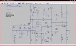
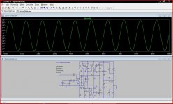
The circuit (which is just a doodle) initially has a DC servo and simulates just fine. This is picture #1 below. I then record the DC voltage at the servo output and sustitute the servo with a fixed voltage source. Again the simulation is fine.
Now for the strange part.
Not wanting the servo I start to delete it component by component using the "scissors" to remove each bit. When I get as far as deleting the opamp or V1 the main circuit suddenly fails to simulate. The main amp output just rises to the positive rail. It also ends up with a B-E voltage of 30 volts across Q1 (Emitter most negative). I can delete the 1 Meg, and the 0.1uF and V2 and their traces and the circuit is still fine. When I come to delete either the opamp or V2 it fails.
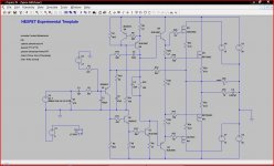
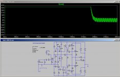
I can get as far as in picture 2. Up to this point the circuit simulates correctly. If I now delete anything else to do with the servo it fails. I even altered the voltage V1 to zero and that made no difference either.
Is it me") or is there a glitch somewhere ? I can't see where I am going wrong.
or is there a glitch somewhere ? I can't see where I am going wrong.
The circuit (which is just a doodle) initially has a DC servo and simulates just fine. This is picture #1 below. I then record the DC voltage at the servo output and sustitute the servo with a fixed voltage source. Again the simulation is fine.
Now for the strange part.
Not wanting the servo I start to delete it component by component using the "scissors" to remove each bit. When I get as far as deleting the opamp or V1 the main circuit suddenly fails to simulate. The main amp output just rises to the positive rail. It also ends up with a B-E voltage of 30 volts across Q1 (Emitter most negative). I can delete the 1 Meg, and the 0.1uF and V2 and their traces and the circuit is still fine. When I come to delete either the opamp or V2 it fails.
I can get as far as in picture 2. Up to this point the circuit simulates correctly. If I now delete anything else to do with the servo it fails. I even altered the voltage V1 to zero and that made no difference either.
Is it me
or is there a glitch somewhere ? I can't see where I am going wrong.Attachments
can you remove the 3.1V error correction (you can call it bias if you want) and replace it with the normal ground referencing resistor to allow the input bias current to flow to source/ground.
The amplifier should then bias itself to a reasonable output offset and you can then apply error correction to that if needed.
Once that is done, maybe then Spice will allow you to delete the last of the DC servo components and any definitions that go with them.
BTW,
may I remind you I am not a prepackaged simulator software user.
The (very simple) modeling I do, is on my own software.
You still have that forced error correction.
That rise in voltage looks like charging of C1 (?)
Let the input find it's own bias for the input offset current.
I agree it does look like C1 charging. Then there is the 30 volts across B-E of Q1. That doesn't sound right in that I would expect it to break down or zener at around 8 volts although I guess that's maybe a "model issue".
Is it a +3V or -3V on the base of the input transistor?
It's minus 3
Is it?It's minus 3
Trace the current flow from Q1 emitter through the transistor to it's base and then to source/sink/ground.
To complete that route you must add that ground referencing resistor.
What voltage would you expect on the base PIN?
That 30V is the output voltage after the amplifier has applied it's DC gain.
The input error could be very much smaller, just a few tens of millivolts of input error, could cause the output offset to rocket.
The amp has a gain of 1 at DC and so any change in the bias voltage is reflected in the output. It doesn't sit on a knife edge at all like a differential amp.
Bias,
-3 volt gives 0 volt output
-2 volt gives + 1 volt output
-1 volt gives +2 volt output
and
-4 volt gives -1 volt output
-5 volt gives -2 volt output
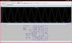
The circuit works. It's why the totally unconnected and unrelated components upset the simulation.
I tried the 47K to ground and it works fine, just with a small DC offset. [Going back and using the same circuit I started out with, I set V8 to give zero volts bias (same as ground) and that was OK too as shown here. As expected it gave the same result as 47K to ground].
Continuing with the circuit and the 47K to ground I then put the bias voltage source back and then it all goes to pot again.
Attachments
Last edited:
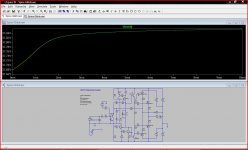
It comes up after about 240ms (I got rid of your 16 for Ncycles of V5) but it is odd that that LTspice is still thinking that your servo is there until you remove the op-amp (you can remove the voltage V1 and replace it with a wire and it will still start immediately).
You also get the delay if you replace the op-amp with another device,
You also get the delay if you replace the op-amp with another device,
Attachments
Last edited:
Leaving ICs placed without supplies can yield some really strange effects. Basically you can't do it. My guess is that it's affecting how the bias points are being calculated in a 'seemingly' beneficial way.
Delete all the hangnails and use something like .ic v(n020)=-1.8 (or zero) and go from there. Might want to consider how the circuit will actually start up.
EDIT: Ooops that .ic doesn't clean things up as much as I thought without leaving C6 at 1u like I had it for test. Somewhere around there is the trouble though..
Last edited:
Try a 1n4148 to clamp E-B reverse bias on Q1
Mmmm
Top solution Mr E
So whats going on I wonder. Can the program having run with the servo must somehow be leaving something behind even when run afresh after altering things.
- Status
- This old topic is closed. If you want to reopen this topic, contact a moderator using the "Report Post" button.
- Home
- Design & Build
- Software Tools
- Spice oddity. Is it me or a glitch ?