Look here, this seems to be the equivalent topology to what you have in mind :
phonostage
General information :
Cut and Thrust: RIAA LP Equalization | Stereophile.com
And in LTspice, a reference can be simply constructed with an AC voltage source of magnitude 10 connected to an "e"-source (VCVS) with the transfer function given in direct Laplace notation, using the known time constants :
laplace (1 + 318u*s) / (1 + 3180u*s) / (1+ 75u*s)
Comparison with the Stereophile article shows 100% precise accuracy (compare the detailed numbers given in the text) as expected right away, but always better double check
Last edited:
Calculation, for a starting point, is quite straightforward. RIAA EQ is a one decade wide bass shelf (from 50Hz to 500Hz) with a pole on top (at 2.1kHz). Problem is the somewhat ill-defined plate impedance of the tubes for the actual circuit which influences all three time constants, being part of the source impedance the network works upon.
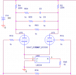
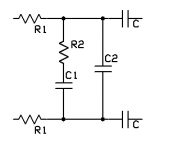
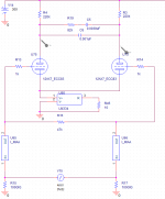
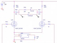
I've attached the topology you want. There's an RIAA calculator here: KAB Electro Acoustics http://www.kabusa.com which you can use as follows.
Connect the two resistors marked R! in my drawing to the 12AX7 plates. For the R1 value in the calculator, use 2 times R1 in the drawing plus two times the source impedance of the driving stage (the formula for the source resistance of a diff amp may be found in Morgan Jones's "Valve Amplifiers" as well as any other standard tube text. The other components can be directly plugged into the KAB calculator.
Connect the two resistors marked R! in my drawing to the 12AX7 plates. For the R1 value in the calculator, use 2 times R1 in the drawing plus two times the source impedance of the driving stage (the formula for the source resistance of a diff amp may be found in Morgan Jones's "Valve Amplifiers" as well as any other standard tube text. The other components can be directly plugged into the KAB calculator.
Attachments
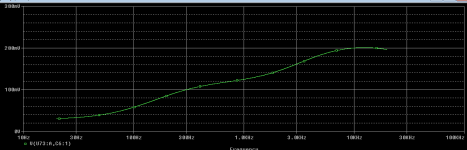
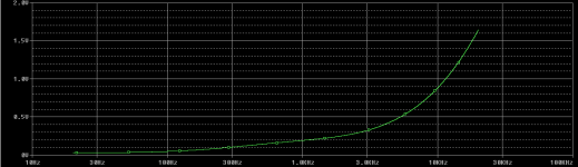
Tried it in simulation. I receive what resembles an RIAA curve, but the voltage differential is supposed to be reasonably flat, as I am running inverse RIAA networks on the inputs, along with the sine wave generator to simulate a cartridge.
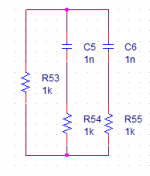
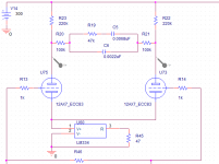
The plate impedance for a 12AX7 is around 70k, in parallel with 220k, and double those quantities is about 560k. I put the values in the calculator and came up with the values in the schematic below. I wondered if I calculated it properly?
The plate impedance for a 12AX7 is around 70k, in parallel with 220k, and double those quantities is about 560k. I put the values in the calculator and came up with the values in the schematic below. I wondered if I calculated it properly?
Attachments
You really do want to incorporate the build-out resistors- that will lower distortion, especially at high frequencies, and reduce the dependence of the frequency response on tube aging and drift. There is something of a noise penalty there, unfortunately. There are also ways around that, but with added complication.
Let's pick 100k as the buildout resistor. The equivalent series resistance is then 200k + 2x RL||Rp. The second term is about 53k, so the total equivalent resistance is 306k. Plugging that into the KAB kalculator, R2 is 44k5, C1 = 7n15, C2 = 2n45.
Let's pick 100k as the buildout resistor. The equivalent series resistance is then 200k + 2x RL||Rp. The second term is about 53k, so the total equivalent resistance is 306k. Plugging that into the KAB kalculator, R2 is 44k5, C1 = 7n15, C2 = 2n45.
The calculated values and 100k build-out resistor flattens out the response better, but those values are not standard. I tried it with other build-out values and the calculator, but the others produce WAY too much deviation.
Is there some other variable somewhere we are missing?
Is there some other variable somewhere we are missing?
I switched the resistors to 62k ohm and re-ran the calculations, as 62k produces values for the RIAA network that are closest to real life component values.
I tried it with a few resistors and none of the combinations produce a flat response. Are we missing something?
I tried it with a few resistors and none of the combinations produce a flat response. Are we missing something?
Attachments
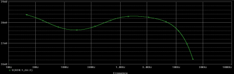
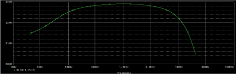
That's about +/-0.3dB, which isn't fantastic, but isn't bad, either. If you put small resistor in series with the shunt cap, you might be able to bring up the top octave.
Keep in mind that the 12AX7 will still be the biggest variable- the assumed plate resistance may easily change by 10-20% tube to tube or as a tube ages. See what effect that has on the RIAA curve. That's one reason I usually use low plate resistance tubes in that spot, but that brings in other complications (especially stability).
Keep in mind that the 12AX7 will still be the biggest variable- the assumed plate resistance may easily change by 10-20% tube to tube or as a tube ages. See what effect that has on the RIAA curve. That's one reason I usually use low plate resistance tubes in that spot, but that brings in other complications (especially stability).
The values may not be standard, but you can build them up out of standard values using paralleling.
Useful to have one of those 3x 365pF variable tuning caps from an old a.m. radio.
- Status
- This old topic is closed. If you want to reopen this topic, contact a moderator using the "Report Post" button.
- Home
- Design & Build
- Software Tools
- RIAA Network Transfer Function