I've recently ran into something very odd.
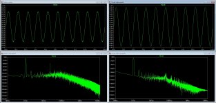
The plots doesn't seem to match the fft?
Look at this and tell me what you see?
The left simulation appears to have a ragged response, really ugly.
The fft shows much better than the sim on the right with the smooth nice looking curve?
What am I missing here?
Ok, I'll give a hint...
The left sim uses a smps @ 23kHz while the right one uses idealized voltage sources.
Wich would sound better? Things like this makes my head spin.
Attachments
Last edited:
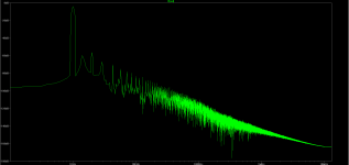
I guess I can treat you to another fft as well, this one represents the previous sim on the right but with a simmed smps @ 23kHz. (The smps model is ran with the tube circuit)
Would the superimposed 23kHz ripple be audiable in any way?
I don't have the right terms for it, harmonics or modulations of sort lower in frequency but generated by the switching frequency?
If the 23kHz ripple is harmless the left sim is one magnitude better than the right one, if it's harmful the right one (with a really good psu) might be a better solution?
(The plot in this post shows the worst of both cases, the right sim with a 120mVpp 23kHz ripple on the B+.)
Attachments
I'm asking on how to interpret graphs since the circuits themselves are protocircuits nothing more.
If I can't read the output the sims will mean very little.
What am I doing...
I'm comparing a couple of different topologies for DC-coupled tube buffers with smps.
I have a long term project building a digital preamp with dsp and tube output stages.
Since it'll be 8 channels and fully balanced, the difference beween using one triode or 4 per channel will be substantial, both the workload and the financial part.
I guess I'm trying to figure out if the cheap and simple solution is good enough?
Is -60dB good enough? (I have a feeling I should be aiming for -80dB if I want silence)
Will the HF ripple be audiable in any way?
Lots of questions but I figured the plots were a good place to start.
the 23KHz could cause problems several ways, most "audible" will involve intermodulation distortion prodcuts which can be below the 23 KHz
try a 20 KHz sine with the circuit showing 23 KHz ripple - you will most likely see a 3 KHz IMD difference product, simialrly with 10 KHz
try a 20 KHz sine with the circuit showing 23 KHz ripple - you will most likely see a 3 KHz IMD difference product, simialrly with 10 KHz
Try just doing an FFT on a sine wave. You'll be surprised by the inaccuracy of the FFT. I can easily get LTSpice to show -60dB harmonics with a pure sine wave. With a few tweaks, you can get that substantially lower, but I still wouldn't trust harmonics below -60dB or so.
Each of these changes improves the accuracy of the FFT:
Increase the simulation time.
Reduce the maximum timestep (1u is a good starting value.)
On the FFT menu, increase the "Number of data point samples in time" by 2 or 3 clicks.
Each of these changes improves the accuracy of the FFT:
Increase the simulation time.
Reduce the maximum timestep (1u is a good starting value.)
On the FFT menu, increase the "Number of data point samples in time" by 2 or 3 clicks.
I find the fft highly accurate with good sim, fft settings - a sine source itself should have better than -150 dB floor
add the .option plotwinsize=0 directive
always use an integer number of periods of the stimulus, easy if you sim to a integer ms length, say 10 mS with integer KHz input
Blackman window works well but requires >4x periods to completely resolve frequencies
sometimes settling time is required so you may need to take the fft over a specified time, or change the start saving data time in the .tran to allow for settling
max time step should be smaller than any gain device Ft, feedback loop gain intercept, and for high fft resolution give >10k points per period
there is no need to exactly calculate the max step since the sim will take variable steps as required by accuracy setting anyway - the point used for the fft are interpolated to the exact sampling time - the order of the interpolation filter is what you're setting with the fft Binomial Smoothing "points" setting
Try just doing an FFT on a sine wave. You'll be surprised by the inaccuracy of the FFT. I can easily get LTSpice to show -60dB harmonics with a pure sine wave. With a few tweaks, you can get that substantially lower, but I still wouldn't trust harmonics below -60dB or so.
Each of these changes improves the accuracy of the FFT:
Increase the simulation time.
Reduce the maximum timestep (1u is a good starting value.)
On the FFT menu, increase the "Number of data point samples in time" by 2 or 3 clicks.
Turn off compression..
I use 10n max time steps when I am going to do an FFT on a simulated waveform. (Quick and dirty set up) JCX's excellent advise will probably give the best results.
Member
Joined 2009
Paid Member
I've seen plots like this and invariably it's how I have spice set up. The advice from jcx matches my experience. I've also noticed that you need to go into the 'tools' menu, open the 'control panel' and disable compression. I think they've changed how this works in the latest revision because I find I have to disable it fairly often as if the default is always-on. With compression turned off my fft curves clean up a good deal.
edit: kevin posted as I was writing....
edit: kevin posted as I was writing....
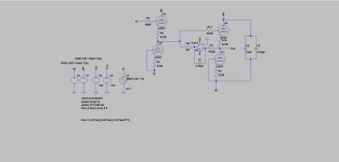
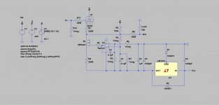
Here are two framegrabs for the fast sims.
If I run a full sim with the smps it takes a looooong time.
Like I said earlier, this is nothing fancy and definately not optimized in any way.
I'm almost a little ashamed to post these schematics.
If I run a full sim with the smps it takes a looooong time.
Like I said earlier, this is nothing fancy and definately not optimized in any way.
I'm almost a little ashamed to post these schematics.
Attachments
As soon as I posted the circuits the thread went cold. 
Let's bump it and see if anyone's anything to say?
The 23kHz switching frequency is adjustable, I can crank it up if it's too close to the audiable spectrum.
120mVpp (23kHz @ B+) is the result of nearly no filtering at all, how low is low enough?
How low should it be at the output to be classified as inaudiable? It's already outside ordinary hearing just from being 23kHz.
Is -60dB (-55/-65) for the hamonics good enough?
How low is an acceptable noise floor? (-60dB or maybe -80dB) I would like it to be quiet.
And last but not least...
I realise this is only a sim and everything will look different irl.
Using a sim as a startingpoint allows me to discard the worst ideas instead of wasing money and time on building it.
Alas the question is still how to interpret the graphs and what boudaries to set up as acceptable/good?
(The circuits are open for change.)
Cranking up the switching frequency is doable, that's one of the reasons I started the thread in the first place to get some advice on that sort of thing.
I know class-D amps usually use something in the 300kHz area but being a psu I wasn't sure how picky I need to be?
If it's all about lowering the noise I could just as well add a filter and keep the "fast and dirty" supply at a lower frequency. (It's super cheap and the transformer alone for a linear supply would cost more than the entire smps.)
If intermodulation will wreck havoc to the music signal it's worth upping the rate.
So I'd rather know what the problem is before I try and find a cure.
As for the tandem CF's, it'n not even a circuit of my own devising. It's a ripoff from a respected electronics designer, I'm just toying with ideas to see what I can come up with.
A CF's input impedance should be in the megaohm range.
So what if the output impedance of the first sage is a little on the high side?
You might be 100% correct in it being a bad idea but it would be more helpful to explain why it's so bad.
I can live with losing some voltage, heck if I wanted a large voltage swing I wouldn't be looking at buffers.
Compression is turned off now, I used to do it that way earlier but I forgot about it.
I'll take a look at plotwinsize and see what it does.
First I learn the mecanics then I start my own design. As I stated in the beginning, I'm a no0b and I'm here to learn.
Try just doing an FFT on a sine wave. You'll be surprised by the inaccuracy of the FFT. I can easily get LTSpice to show -60dB harmonics with a pure sine wave. With a few tweaks, you can get that substantially lower, but I still wouldn't trust harmonics below -60dB or so.
Only if you set it up badly. The biggest culprit is not turning off compression - I still don't know why the default is ON. Add this spice line to your schematic:
.option plotwinsize=0
Cheers
Ian
Turning off the compression did clear some things up.
I might just go ahead and build the small simple circuit just for the heck of it and see how it compares to the sim?
Any suggestions for tweaking the circuit with one tube? I'd be happy for any advice I can get. The goal is to keep it dc-coupled and simple. (And sound good)
I might just go ahead and build the small simple circuit just for the heck of it and see how it compares to the sim?
Any suggestions for tweaking the circuit with one tube? I'd be happy for any advice I can get. The goal is to keep it dc-coupled and simple. (And sound good)
Re: leftmost schematic your dc servo design is not good, it will significantly degrade the AC performance of your first stage - need to rethink that. Hint: That 4.7K resistor is part of the load for AC or DC signals present on the output of first stage, makes your current source quite pointless..
You could probably get good AC performance right down to 5Hz or so with a single tube and coupling cap without the complexity and the danger of unintended interactions possible with these designs. Sometimes the best circuit is the least complex one that will do the job whether or not it has a coupling capacitor in it somewhere.
You could probably get good AC performance right down to 5Hz or so with a single tube and coupling cap without the complexity and the danger of unintended interactions possible with these designs. Sometimes the best circuit is the least complex one that will do the job whether or not it has a coupling capacitor in it somewhere.
Is -60dB good enough? (I have a feeling I should be aiming for -80dB if I want silence)
Will the HF ripple be audiable in any way?
Lots of questions but I figured the plots were a good place to start.
Most of us who are over 16 years old, if you put a pure and loud 23KHz signal into the headphone we could not hear it at all. OK so a few people claim super-human hearing. Just double the SMPS frequency to 46K.
Do your speakers up up to 23K? Do they need to? Try it. Get a signal generator and even a cheap "chip amp" and listen to a pure 23K sine wave. I did this and found the like most people I can't hear it at all. Be careful when testing not to have any lower frequency mixed it. Put a microphone on a scope or something as a control.
Last edited:
- Status
- This old topic is closed. If you want to reopen this topic, contact a moderator using the "Report Post" button.
- Home
- Design & Build
- Software Tools
- LTspice and simulating tube circuits?