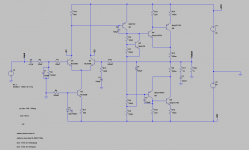
Trying to do a little THD simulation with LTSpice.
Simulating Rod Elliotts P3A I get huge input sine wave THD which ofcourse screws up the whole simulation.
See attached pictures.
Did I overlook some obscure LTSpice setting?
Simulating Rod Elliotts P3A I get huge input sine wave THD which ofcourse screws up the whole simulation.
See attached pictures.
Did I overlook some obscure LTSpice setting?
Attachments
Last edited:
It works now, great. 
Thanks alot for the help.
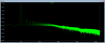
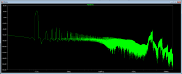
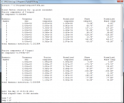
But as the picture shows, at 1kHz, 50W into 8 ohm load the THD is above 0.1%.
And at the same power into the same load but at 20kHz the THD is 1.3%
Would like to get atleast the 1kHz THD below 0.01 if possible and the 20kHz THD below 0.1
But now I can get started.
Thanks alot for the help.
But as the picture shows, at 1kHz, 50W into 8 ohm load the THD is above 0.1%.
And at the same power into the same load but at 20kHz the THD is 1.3%
Would like to get atleast the 1kHz THD below 0.01 if possible and the 20kHz THD below 0.1
But now I can get started.
Attachments
Last edited:
A good start would be setting the output stage idling current. The ratio of R7 to R9 looks wrong, IMO.
Indeed it is. It was just a start to get the simulation going.
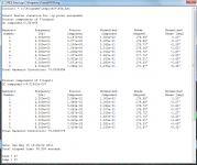
Well after reducing R7 to 450 Ohm, which gives an output stage idle current of about 60-65 mA THD-20 at 50 W into a 8 Ohm load is now down to 0.8%.
Better but not perfect, however the THD-1 should be a good deal better as well.
And indeed it is, THD-1 at 50 W into a 8 Ohm load is now down to 0.08%.
Better but not perfect, however the THD-1 should be a good deal better as well.
And indeed it is, THD-1 at 50 W into a 8 Ohm load is now down to 0.08%.
Last edited:
An interesting thing is that eventhough Rod Elliott advises to use between 20-100mA idle current for the output stage a simulation with even higher idle current shows a definate improvement.
250mA output stage idle current gets THD-20 numbers of around 0.65% at the same 50 W in to an 8 Ohm load.
Guess going higher than recommended is a good thing, as long as you have enough heatsinking.
250mA output stage idle current gets THD-20 numbers of around 0.65% at the same 50 W in to an 8 Ohm load.
Guess going higher than recommended is a good thing, as long as you have enough heatsinking.
Self, Cordell's amplifier design books are a big help learning how to reduce distortions
currrent mirror load in the diff pair collectors equalizes diff pair current for less input stage distortion - the 1st step I'd take since increased loop gain is less useful if the diff pair can't accurately measure the error V to apply negative feedback
two more steps
"beta enhanced " VAS - a ef buffer between the diff pair out and the VAS Q with Cdom enclosing both
and a ef buffer btween the VAS out and the (compound) output Q - for a total of 3 Q giving current gain after the VAS
I have posted a Ltspice version of one of Bob Cordell's book's example circuits to explore stability/compensation in http://www.diyaudio.com/forums/soli...lls-power-amplifier-book-134.html#post2420438 (my stability example circuit derived from Bob's posted asc http://www.diyaudio.com/forums/solid-state/171159-bob-cordells-power-amplifier-book-119.html post 1184)
this uses all 3 tricks suggested but with straight "triple" ef/darlington output, just rearanging the last 2 output Q for your CFP and adjusting bias should be quick
Last edited:
- Status
- This old topic is closed. If you want to reopen this topic, contact a moderator using the "Report Post" button.
- Home
- Design & Build
- Software Tools
- LTSpice way too high input sine wave THD