Hi,
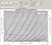
since there was no reply to my inquiry I had to come up with my own solution. Norman Koren was so kind as to run parameters I had extracted from the datasheet through his Tuparam software. The resultant model needed some tweaking, for which I used James E. Lanier's program PSPICE_Calc . The match is not perfect, but approximates the normal operating range (Ug=[-8v..-12V]) reasonably well:

The thick lines are the ones from the datasheet, the thin ones show what the model parameters do.
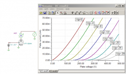
I plugged these data into a TINA-TI model and created a TINA macro for it.
And here is the test run under TINA-TI:

Again, this will require more work, but it is a start. Thanks again to Norman and James without whose software I would not have tackled this project.
Fred
since there was no reply to my inquiry I had to come up with my own solution. Norman Koren was so kind as to run parameters I had extracted from the datasheet through his Tuparam software. The resultant model needed some tweaking, for which I used James E. Lanier's program PSPICE_Calc . The match is not perfect, but approximates the normal operating range (Ug=[-8v..-12V]) reasonably well:

The thick lines are the ones from the datasheet, the thin ones show what the model parameters do.
I plugged these data into a TINA-TI model and created a TINA macro for it.
Code:
*TEXAS
.SUBCKT 6S4A P G C ; P G C
+ PARAMS: MU= 16.5 EX= 1.344 KG1= 1090 KP=133
+ KVB= 4.5 VCT=0.00 RGI=1000
+ CCG=4.9p CGP=2.9p CCP=1.1p ; .7PF added to adj. pins, .5 to others
E1 7 0 VALUE=
+{V(P,C)/KP*LOG(1+EXP(KP*(1/MU+V(G,C)/SQRT(KVB+V(P,C)*V(P,C)))))}
RE1 7 0 1G
G1 P C VALUE={(PWR(V(7),EX)+PWRS(V(7),EX))/KG1}
RCP P C 1G ; TO AVOID FLOATING NODES IN MU-FOLLOWER
C1 G C {CCG} ; CATHODE-GRID
C2 G P {CGP} ; GRID-PLATE
C3 P C {CCP} ; CATHODE-PLATE
D3 5 C DX ; FOR GRID CURRENT
R1 G 5 {RGI} ; FOR GRID CURRENT
.MODEL DX D(IS=1N RS=1 CJO=10PF TT=1N)
.ENDS
Again, this will require more work, but it is a start. Thanks again to Norman and James without whose software I would not have tackled this project.
Fred
Last edited:
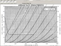
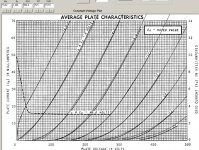
Amended model (better match for -12>Ug>-28V):

And here is the TINA-TI model:

And here is the TINA-TI model:
Code:
*TEXAS
.SUBCKT 6S4A P G C ; P G C
+ PARAMS: MU= 17.18 EX= 1.267 KG1= 873.1 KP=105.3
+ KVB= 31.7 VCT=0.00 RGI=1000
+ CCG=4.9p CGP=2.9p CCP=1.1p ; .7PF added to adj. pins, .5 to others
E1 7 0 VALUE=
+{V(P,C)/KP*LOG(1+EXP(KP*(1/MU+V(G,C)/SQRT(KVB+V(P,C)*V(P,C)))))}
RE1 7 0 1G
G1 P C VALUE={(PWR(V(7),EX)+PWRS(V(7),EX))/KG1}
RCP P C 1G ; TO AVOID FLOATING NODES IN MU-FOLLOWER
C1 G C {CCG} ; CATHODE-GRID
C2 G P {CGP} ; GRID-PLATE
C3 P C {CCP} ; CATHODE-PLATE
D3 5 C DX ; FOR GRID CURRENT
R1 G 5 {RGI} ; FOR GRID CURRENT
.MODEL DX D(IS=1N RS=1 CJO=10PF TT=1N)
.ENDSHi Pryanick,
here are two sites to get you started:
Improved vacuum tube models for SPICE, Part 1
Spice Models
Most models you find browsing the net were made for SPICE and do not necessarily work with TINA-TI. Just insert "*TEXAS" as the first line and see if you can make them work...
BTW: Nice avatar!
Warm regards,
Fred
- Status
- This old topic is closed. If you want to reopen this topic, contact a moderator using the "Report Post" button.
- Home
- Design & Build
- Software Tools
- 6S4/6S4A TINA-TI/SPICE model?

