I have been using Circuitmaker 2000 for several years to do simple sims and now I am getting into an area that I need some instruction and information. 
Can anyone explain the NSD function and the associated measurements on the scale? As well as some info on the Fourier Analysis function along with its associated scale.
In my amplifier design the NSD displays a nice smooth ramp from 0 to 2.000fV^2/Hz @ 16hz then tapers to a flat 2.250fV^2/Hz @ 64hz then at 131.072khz it slowly ramps up to 3.250fV^2/Hz @ 4.2meghz and of course rises sharply to peak 24.50fV^2/Hz @ 24meghz then sharply declines to 0.500fV^2/Hz @ 42meghz then to a smooth decline down to 0 @ 264.4meghz.
On the Fourier Analysis tab my amp shows it starting out at 34mV then droping straight down to 0mV @ .1Hz then obviously flat at 0mV all the way across.
Can someone put all that in a decent verbage that I may find revealing? If more info is needed on my circuit I can do so, just ask.
I respect/appreciate everyone here.
Karl
In Fourier, X is frequency, Y is magnitude of the signal at that frequency. For instance, in a fourier it can be seen that a square wave can be made from many sine waves, each being an odd harmonic of the fundamental frequency.
As for noise analysis, I don't understand it either. You may know more than I do. I tried looking up noise papers by professor Leach, but it's all bizarre math stuff. If you have had some good math classes you should look up Leach's webpage.
BTW, as I understand it, a proper simulator shouldn't show noise in the Fourier analysis. IE, noise is only simulated when you ask for it because most of the time it's just in the way. So the noise floor in your FFT may actually be produced from digital artefacts and maximum resolution when processing. However I have never used CircuitMaker so I can't be sure.
Why not post some screenshots of what you're looking at (the graphs). And often times, I've seen people asking questions like this when they were simulating the circuit wrong; the graphs were working right but the circuit was set up wrong. So it may be helpful to post a screenshot of your circuit too.
- keantoken
Thank you kean-
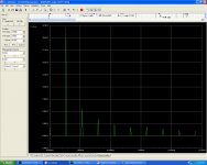
Screen shots of NSD and Fourier:
The circuit in question uses a simple LTP with CMs, active CCS with a buffered VAS all mirrored topo with bias . No OPS at the moment.
Reference input and node is a sign wave 2Vp-p the output node is taken from the input of a generic 1:1 gain stage block feeding the NFB.
using +/- 27.6V Rails decoupled.
Attachments

Last edited:
It may be more useful to set the axes on the fourier graph to logarithmic. That is how most attachments on DIYAudio are formatted. In most amps, harmonics above the 3rd aren't visible on a non-logarithmic graph. This may be a sign of improper operation.
Same goes for the noise graph, you will see more information. Also, those spikes look like resonance peaks. It looks to me like the resolution (number of data points) taken by the graph isn't large enough to show how high they really are, as you can see by the blunted misshapen peaks. If you turn up the resolution it may be more accurate.
- keantoken
Thanks again kean-
It seems as though the Fourier is inhearantly dead set on a linear X axis (non-changeable, log selections are greyed out), y axis has various selections that seem to only change the y side bar designations, no change in the displayed data. (user input can only change freq to be tested and # of harmonics desired)
I even changed the # of cycles to be ran, and nada-no change.
The only parameters allowable to be changed in the NSD is fundamental freq (this is of course used to see at a specific freq, so I did not want to change this), test points (I changed from 5-10-50-100-200-500), Linear-Decade-Octave (checked with all 3). always gives the same graph shape except on linear scale (linear definitly usless at this point).
I really apreciate the help.
Thanks again.
Karl
Last edited:
If you are using a trial version that may be why.
There are a lot of folk using LTSpice, and it's what I use. It's freeeeeeeeeee. And guys here will contend that it's not cheezy.
An alternative I'm looking at is superspice:
AnaSoft - Analoge Simulation - SuperSpice
- keantoken
There are a lot of folk using LTSpice, and it's what I use. It's freeeeeeeeeee. And guys here will contend that it's not cheezy.
An alternative I'm looking at is superspice:
AnaSoft - Analoge Simulation - SuperSpice
- keantoken
Thanks again,
Most likely that is the case then. Trial version been hacked so at least I have a basic spice program that works on the basics only. Looks as though I have advanced into the next level and I will have to spend some to make some.
I like all the nice features. I think I may have that one in my favs link, if not it will be. I will be looking harder at that one now.
Again I thank you for helping me.
Karl
It looks like SuperSpice is the next level as far as convenience maybe. For effective simulation, I'm not sure. It includes all the default western SPICE models, but not the japanese ones, which tend to be passably accurate. It only allows temperature steps and sweeps, but doesn't perform a realtime temperature analysis. This is a real downer. Without real time self-heating effects taken into account for semiconductors, your circuit will be very different from real life in terms of linearity and what you can get away with thermally. Another one is the lack of an effective management of the inclusion of parasitics. With most simulators you must enter in trace parasitics in a slow, tedious manner. This would be far simpler if you could simply right click on a wire and give it an LCR value, or join it with another trace to form a transmission line or inductively coupled traces. Won't necessarily be perfect, but it will be more realistic than what we have now. These are the features I'm waiting for in SPICE.
If you want to try out LTSpice, Email me and I'll help you get through the tough part.
- keantoken
If you want to try out LTSpice, Email me and I'll help you get through the tough part.
- keantoken
Hi Karl
I use an old "Student" version of Circuitmaker.
On the output screen there's a button that brings up a "Settings" screen, where you can select "Decibels" for the vertical scale. Perhaps your version has something similar?
Btw, I wouldn't recommend the old "Student" version as it's more than slightly buggy (but very easy to use). In comparison LTSpice is very good, but an absolute pain to use.
Cheers - Godfrey
Attachments
I don't think anyone has answered this question.what does fV2^2/Hz translate into?
White noise has a uniform power spectrum - to find the noise power within a particular bandwidth you multiply the noise power density by the bandwidth. Noise power goes like voltage squared (like all power with a fixed resistance). Often in electronics we are more interested in voltage than power, so noise spectral density can be expressed as V^2 instead of watts. So NSD in V^2/Hz means that to get the RMS noise voltage you multiply by the bandwidth (that is the /Hz part), then take the square root (the V^2 part).
I'm not sure what the f and the first 2 are for.
Thank you for that explaination. At least that gives me a the basics for the noise density>voltage correlation. And yes, bypassing a generic 'power' reading has more than one advantage. As everyone should know: 1) Power is a relative term. 2)Power is only meningful if most, if not all parameters are known and/or specified.
The student version that you have a scr-shot of is definitly more limited. CM2K pro has a few more user friendly buttons. I lost the reg# after a few years and several moves and now I have to deal with the trial period, then reload MSWin, trial, reload, trial, relo... PITA. LTSpice is definitly nice but no where near being user friendly. When I say friendly I mean (create component - import spice data - Save component with inherant spice data - create new circuit - sim it). It would be really nice if a developer designed a cross-platform program that could extract user defined data from PDF's to be used in spice. I know Adobe would probably loose multi-billions of dollars letting another program access data points within their pdf structure. However, it would benifit many, for the common advancement of our human race.
Design Spark V3 is really nice as a Sch/pcb freebee with 3D modeling and the ability to only export to LTSpice. But it would be a really robust program if the import and export could be a 2-way freeway! (12 lane Interstate standards)
The student version that you have a scr-shot of is definitly more limited. CM2K pro has a few more user friendly buttons. I lost the reg# after a few years and several moves and now I have to deal with the trial period, then reload MSWin, trial, reload, trial, relo... PITA. LTSpice is definitly nice but no where near being user friendly. When I say friendly I mean (create component - import spice data - Save component with inherant spice data - create new circuit - sim it). It would be really nice if a developer designed a cross-platform program that could extract user defined data from PDF's to be used in spice. I know Adobe would probably loose multi-billions of dollars letting another program access data points within their pdf structure. However, it would benifit many, for the common advancement of our human race.
Design Spark V3 is really nice as a Sch/pcb freebee with 3D modeling and the ability to only export to LTSpice. But it would be a really robust program if the import and export could be a 2-way freeway! (12 lane Interstate standards
)
Last edited:
- Status
- This old topic is closed. If you want to reopen this topic, contact a moderator using the "Report Post" button.
- Home
- Design & Build
- Software Tools
- Noise Spectral Density and Fouier Analysis